A laser cutting machine

A laser cutting machine and auxiliary workbench technology, applied in laser welding equipment, welding equipment, metal processing equipment, etc., can solve the problem of inability to realize the positioning accuracy of the cutting box, increase the after-sales maintenance cost of enterprises, and increase the maintenance rate of equipment manufacturers and other problems, to achieve the effect of simple structure, elimination of front and rear jitter, and low cost

Inactive Publication Date: 2016-01-20
NANJING HIGH SPEED TRANSMISSION SK NUMERICAL CONTROL EQUIP
View PDF4 Cites 1 Cited by
  • Summary
  • Abstract
  • Description
  • Claims
  • Application Information

AI Technical Summary

Problems solved by technology

Due to the lack of rigidity of the roller chain on the sprocket chain drag exchange device, the chain is prone to elongation and deformation during use, the delay in the response of the sensor switch, and the inertia of the cutting box during movement, etc., it is easy to cause the cutting box and auxiliary The misalignment between the worktables makes it impossible to achieve the positioning accuracy required for the exchange movement of the cutting box or the exchange system is paralyzed due to the failure of the positioning function; it directly reduces the production efficiency of the machine tool and increases the after-sales ma

Method used


Image

  • A laser cutting machine
  • A laser cutting machine
  • A laser cutting machine

Examples


Embodiment

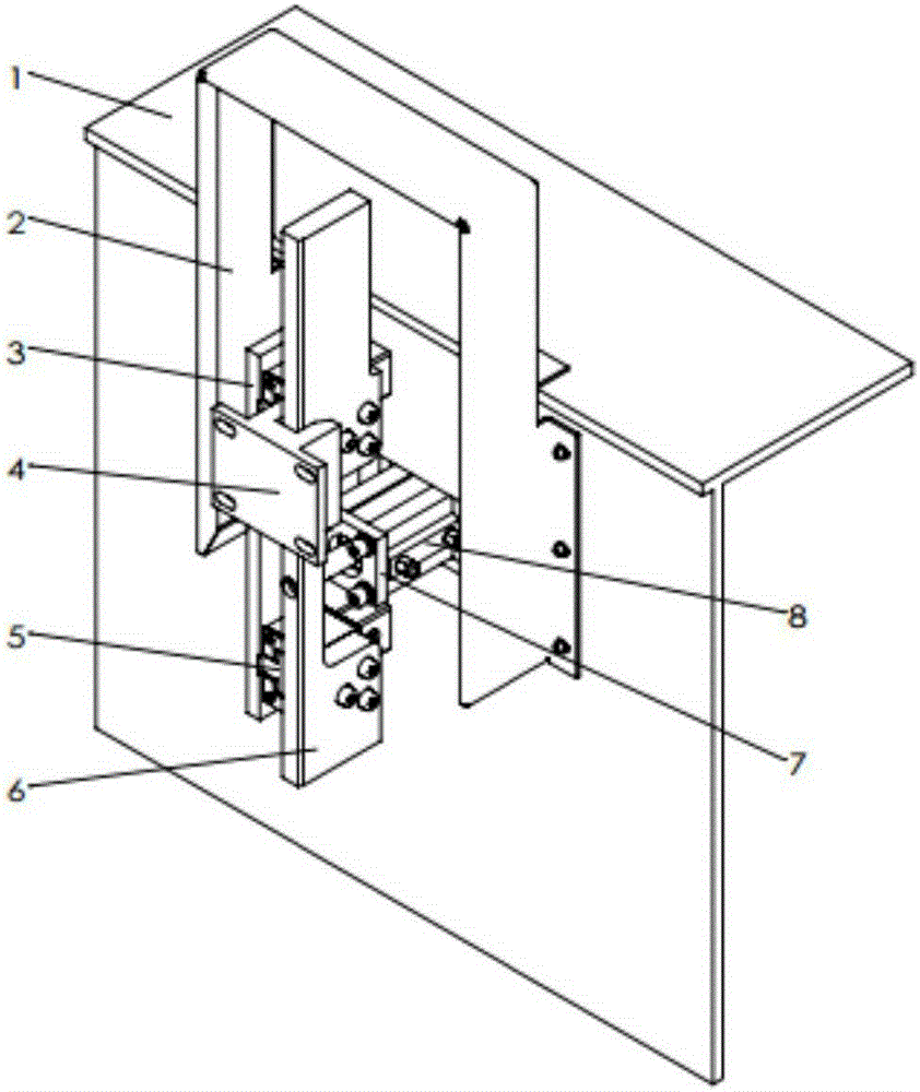
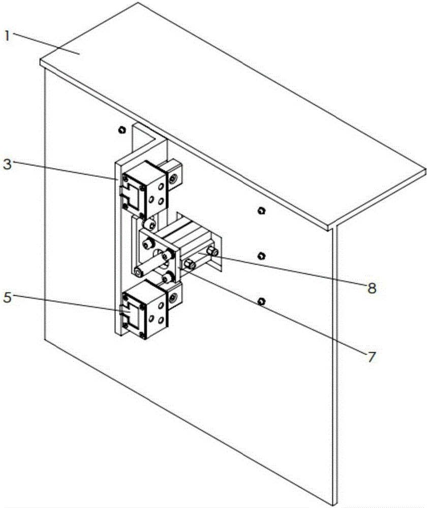
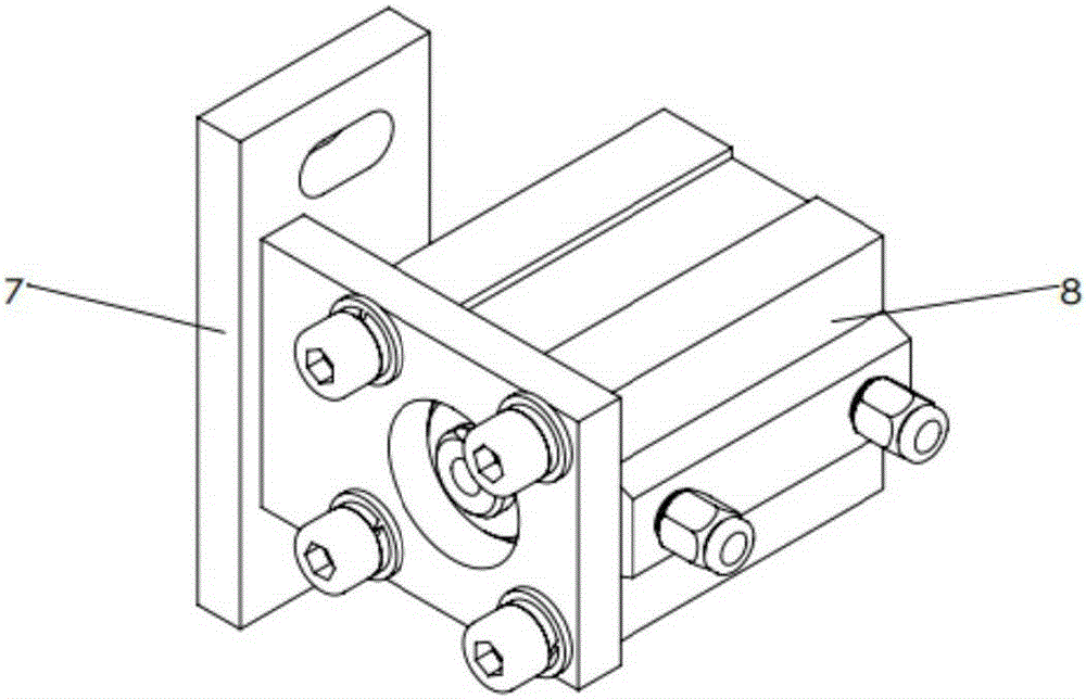
[0032] like Figure 1a and Figure 1b As shown, the present embodiment discloses a laser cutting machine, which includes a cutting box 18 and an auxiliary workbench 1. A side positioning device is provided between the cutting box 18 and the auxiliary workbench 1; the side positioning device is mainly composed of The guide rail slider pair 5 on the 3, the positioning plate 6, the cylinder support frame 7 and the cylinder 8, the positioning block 4 installed on the cutting box and the throttle valve 14, the two-position five-way reversing valve 15, and the muffler 16 , push-in connector 17, pneumatic control system 9 formed by trachea (omitted and not drawn). The protective cover 2 can protect the device, and can also provide safety protection for operating workers. The positioning device has a simple structure and a small overall size, and can be directly installed on the auxiliary workbench 1 of a numerically controlled laser cutting machine tool after being assembled.

[00...


PUM


Abstract

The invention discloses a laser cutting machine. The laser cutting machine comprises a cutting box and an auxiliary worktable, wherein a side positioning device is arranged between the cutting box and the auxiliary worktable and comprises a pneumatic portion and a sliding portion; the pneumatic portion comprises a bottom plate, a cylinder and a positioning block; the bottom plate is fixed on a side surface of the auxiliary worktable; the cylinder penetrates in the side surface of the auxiliary worktable; the positioning block is fixed on a side wall of the cutting box; a cylinder supporting rack which is fixedly connected with the bottom plate is arranged at an end of the cylinder; a piston rod of the cylinder is connected with a positioning plate; the shape of the positioning block is matched with that of the positioning plate, so that a linear kinematic pair is formed; the sliding portion comprises a guide track and a sliding block; the guide track is fixed on the side surface of the worktable; and the sliding block slides on the guide track and is fixedly connected with the positioning plate. In an exchanging jack-up process of the cutting box, the positioning plate extends and is in contact with the positioning block by using the cylinder, and the cutting box which is restrained by the positioning plate moves linearly.

Description

technical field [0001] The invention relates to a laser cutting machine, in particular to a two-dimensional and three-dimensional laser cutting machine. Background technique [0002] Laser cutting technology is more and more widely used in industry due to its flexible processing and quality assurance characteristics, especially the processing of plates. The stable and reliable processing environment is the most popular feature of this technology. In the production of sample parts or batch trial production and the small batch production process before mass production, the application of this new technology can create high profits; The sprocket chain drags the exchange device and the electronic induction switch to ensure the repeated positioning accuracy between the cutting box and the auxiliary workbench. Due to the lack of rigidity of the roller chain on the sprocket chain drag exchange device, the chain is prone to elongation and deformation during use, the delay in the re...

Claims


Application Information

Patent Timeline
IPC IPC(8): B23K26/38B23K26/08B23K26/70
CPCB23K26/38B23K26/702
Inventor 杜玉湘殷志强林文元孔龙辉
Owner NANJING HIGH SPEED TRANSMISSION SK NUMERICAL CONTROL EQUIP
Why Eureka
Try Eureka