Concrete-filled steel tube column top and sandwich concrete composite plate joint and construction method

A steel tube concrete column and concrete technology, which is applied in the direction of construction, building structure, and building material processing, can solve the problems of bulky concrete floors, high cost of steel structures, and low strength, so as to improve integrity, reduce structural weight, The effect of taking into account both construction efficiency and economic benefits

Pending Publication Date: 2021-01-12
辽宁省城乡市政工程集团有限责任公司
View PDF0 Cites 0 Cited by
  • Summary
  • Abstract
  • Description
  • Claims
  • Application Information

AI Technical Summary

Problems solved by technology

[0007] Aiming at the problems existing in the prior art, the present invention provides a joint between the top of a steel pipe concrete column and a sandwich concrete composite slab and a construction method, which can take into account construction efficiency and economic benefits while ensuring the stable connection between the top of a steel pipe concrete column and a sandwich concrete composite slab , avoiding the problems of bulky concrete floors, low strength and high cost of steel structures, reducing the self-weight of the structure, and improving the integrity, stability and earthquake resistance of the slab-column structure

Method used


Image

  • Concrete-filled steel tube column top and sandwich concrete composite plate joint and construction method
  • Concrete-filled steel tube column top and sandwich concrete composite plate joint and construction method
  • Concrete-filled steel tube column top and sandwich concrete composite plate joint and construction method

Examples


Embodiment Construction

[0043] The present invention will be further described in detail below in conjunction with the accompanying drawings and specific embodiments.

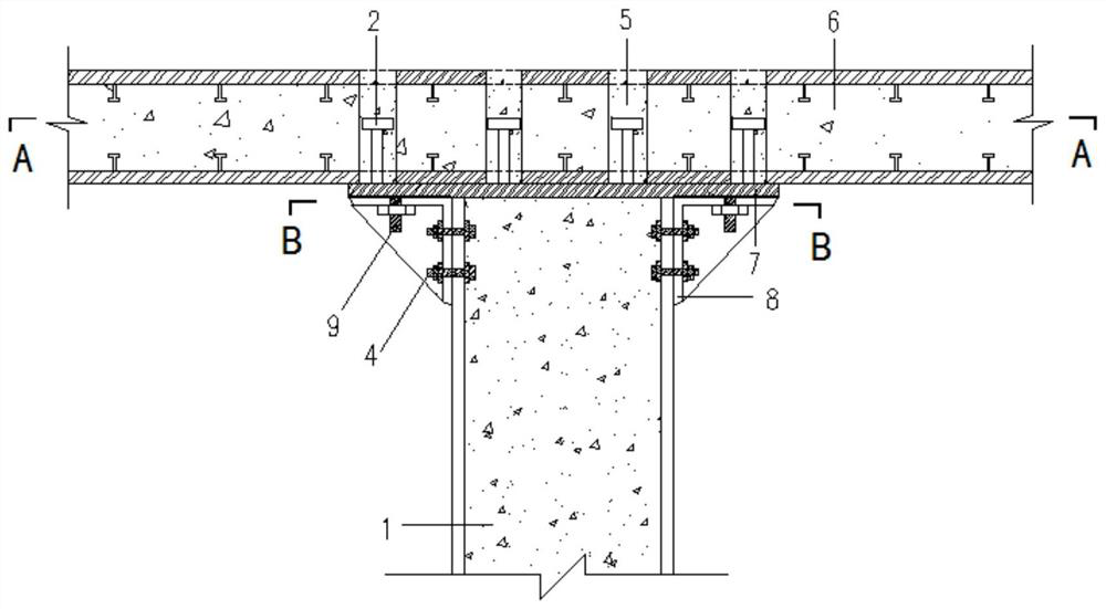
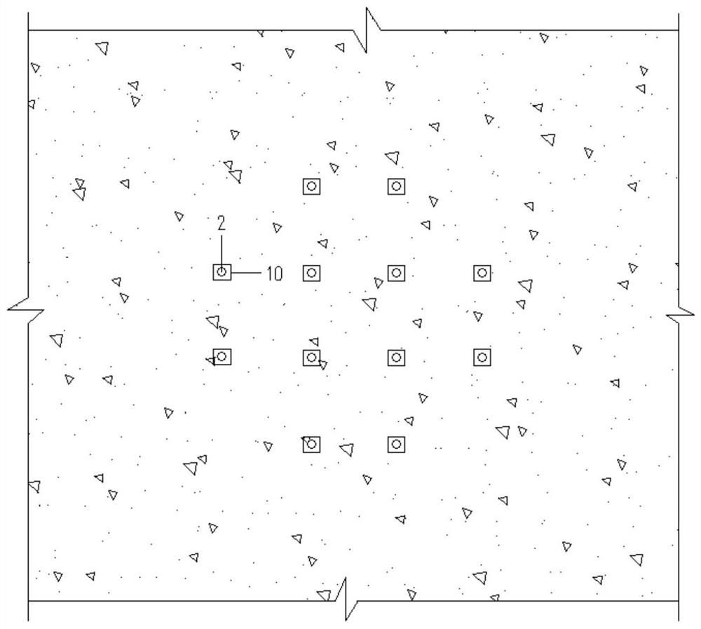
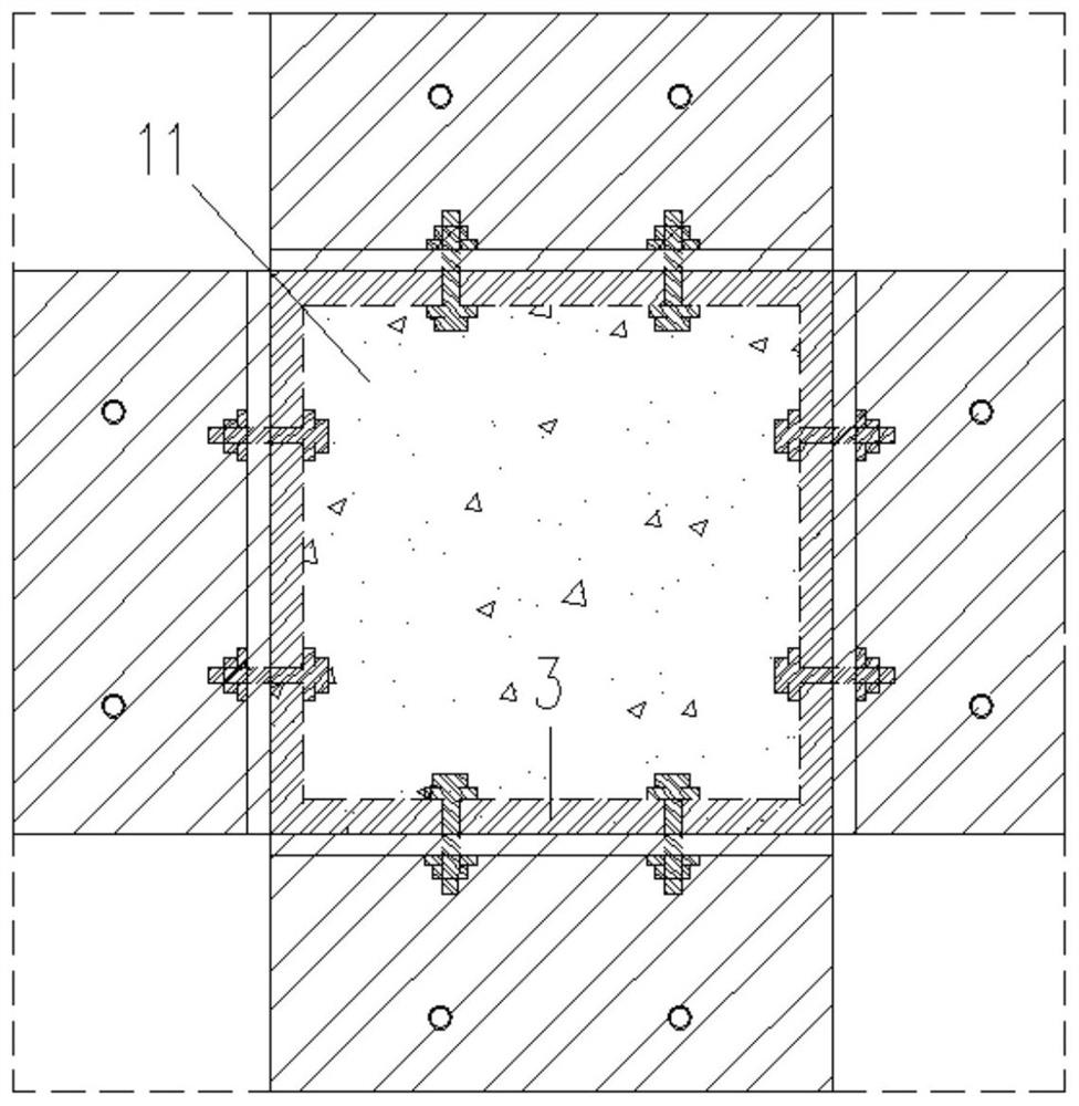
[0044] Such as Figure 1~5 As shown, a joint between the top of a steel tube concrete column and a sandwich concrete composite plate is connected by a steel plate and a stud, including a steel tube concrete column 1, a sandwich concrete composite plate 6, a supporting angle steel 8, a connecting steel plate 7, and embedded bolts 4, Pre-welded screw 9 and stud 2; the connecting steel plate 7 is horizontally welded and fixed on the top of the steel pipe concrete column 1; the supporting angle steel 8 is located between the connecting steel plate 7 and the sandwich concrete composite plate 6, and the vertical legs of the supporting angle steel 8 The steel pipe concrete column 1 is fixedly connected with the embedded bolt 4, and the horizontal leg of the supporting angle steel 8 is fixedly connected with the connecting steel plate 7 throu...


PUM


Abstract

The invention relates to a concrete-filled steel tube column top and sandwich concrete composite plate joint and a construction method. The joint comprises a concrete-filled steel tube column, a sandwich concrete composite plate and a connecting steel plate, and further comprises support angle steel, a pre-buried bolt, a pre-welded screw rod and a stud when a steel plate and stud matched connection manner is adopted, and when a flange plate and high-strength bolt matched connection manner is adopted, a flange plate and a high-strength bolt are further included. The method comprises the steps that when the steel plate and stud matched connection manner is adopted, the concrete-filled steel tube column, the sandwich concrete composite plate and support angle steel are manufactured, the concrete-filled steel tube column is installed in place, the support angle steel is installed, nuts of the pre-buried bolt and the pre-welded screw rod are screwed down, the sandwich concrete composite plate is hoisted in place, and concrete is poured into stud preformed holes; and when the flange plate and high-strength bolt matched connection manner is adopted, the concrete-filled steel tube column is installed in place, the sandwich concrete composite plate is hoisted in place, the high-strength bolt is installed, the nuts are screwed down, and concrete is poured into bolt preformed holes.

Description

technical field [0001] The invention belongs to the technical field of construction engineering, and in particular relates to a joint between the top of a steel pipe concrete column and a sandwich concrete composite plate and a construction method. Background technique [0002] The column-slab structure is a house structure with a load-bearing system composed of columns and floors. It is a special case of a frame structure and is generally made of reinforced concrete. Because there is no beam under the indoor floor of the slab-column structure, it is convenient for the layout of electromechanical pipelines, and can reduce the height of the building. It has the advantages of smooth and concise space and flexible layout. The column-slab structure is suitable for multi-storey factory buildings, warehouses and halls of public buildings, as well as office buildings and residences. [0003] At present, the construction technology of the column-slab structure is mainly based on on...

Claims


Application Information

Patent Timeline
Patent Type & Authority Applications(China)
IPC IPC(8): E04B1/38E04B1/41E04B1/30E04G21/14
CPCE04B1/30E04B1/38E04B1/4157E04B1/4171E04G21/14
Inventor 夏志忠王连广沈功强高海洋赵春雷孔凡利郑立超马洪亮王天嵩刘汉波金佳佳
Owner 辽宁省城乡市政工程集团有限责任公司
Why Eureka
Try Eureka