
Filtering type joint for ball valve

A filter type, ball valve technology, applied in the field of environmental engineering, can solve problems such as unfavorable daily use, water pollution, etc.

Pending Publication Date: 2021-01-12
ANHUI QIFENG MACHINERY & EQUIP
View PDF0 Cites 0 Cited by
  • Summary
  • Abstract
  • Description
  • Claims
  • Application Information

AI Technical Summary

Problems solved by technology

[0002] The faucet with ball valve is a common tap water switch in daily life, and this kind of water valve is often used for household or garden plant irrigation. It has the advantages of low cost, low cost and easy installation. It is also very convenient to use. It has been popular among the public for nearly a hundred years. However, with the development of the times, water pollution is a very serious problem. Most people rely on water supply and drainage filtration from water plants, or spend a lot of money to buy water filter elements and equipment to perform secondary filtration of tap water. This method not only consumes a lot of money to maintain the equipment, but also requires staff to go to the site to replace the filter element, which is not conducive to daily use

Method used


Image

  • Filtering type joint for ball valve
  • Filtering type joint for ball valve
  • Filtering type joint for ball valve

Examples


Embodiment 1

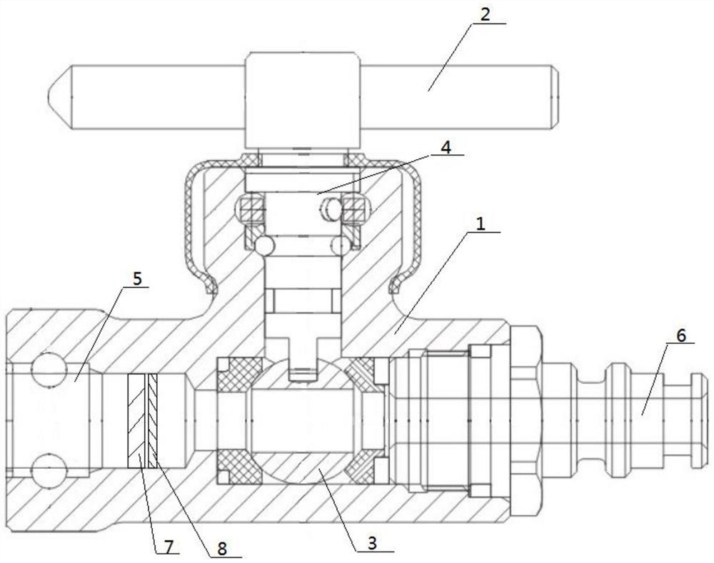
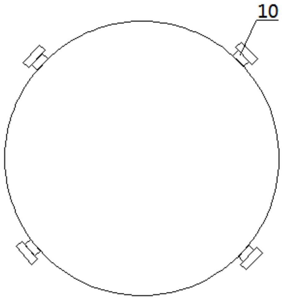
[0023] figure 1 It is a structural schematic diagram of the first embodiment of the filter joint of the present invention, image 3 It is a schematic structural view of the ion exchange layer in the present invention. As shown in Figure 1, the filter part includes an ion exchange layer 7 and a sterilizing layer 8. The ion exchange layer 7 and the sterilizing layer 8 are placed in the cavity in sequence, and the ion exchange layer 7 Four installation buckles are evenly spaced on the side connecting the sterilization layer 8 and the cavity, and the cavity is provided with a sliding groove for buckle access at the corresponding position of the buckle, and the ion exchange layer and the sterilization layer pass through The sliding groove is fitted with the corresponding mounting buckle to be slidably installed into the cavity, and the ion exchange layer is attached to the exchange filter using polystyrene ion exchange resin with exchange properties, such as image 3 The side of t...

Embodiment 2

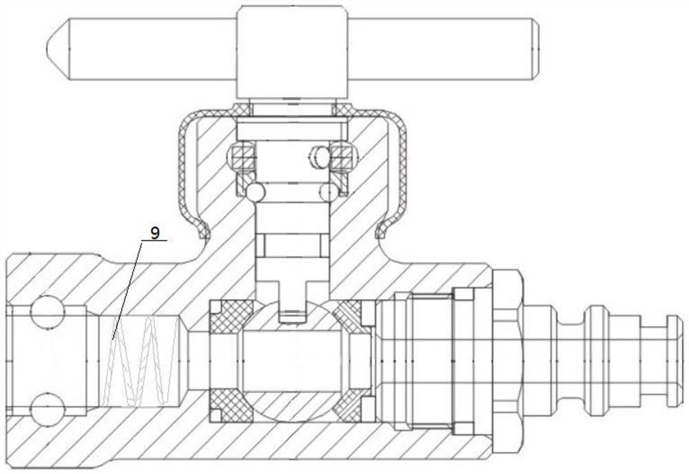
[0025] figure 2 It is a structural schematic diagram of the second embodiment of the filter joint of the present invention, as figure 2 The shown filter part comprises a spiral filter layer 9, one end of the spiral filter layer 9 is fixedly connected to the end of the cavity close to the ball valve, and the transverse length of the filter layer is consistent with the length of the cavity, and the other end of the filter layer is One end is connected to the end of the cavity close to the water inlet. The filter surface of the filter layer is uniformly equipped with granular activated carbon fibers. The water flow from the water inlet enters the ball valve through the spiral filter layer and is transferred to the water outlet. Compared with the method in Example 1, this solution can filter more adsorbable impurities in water, but lacks the effect of ion exchange resin, and is suitable for plant irrigation.

[0026] The installation method of this scheme is that there is a spi...


PUM


Abstract

The invention discloses a filtering type joint for a ball valve. The filtering type joint comprises the ball valve and a joint shell wrapping the ball valve in an inner cavity; a switch connecting rodfor controlling the ball valve to rotate is arranged in the position, located at the top of the ball valve, of the shell; the switch connecting rod is fixedly connected with the top of the ball valve; the bottom of the switch connecting rod is arranged in the joint shell; a water inlet and a water outlet are formed in the two ends, with the center line of the ball valve used as the center line, of the joint shell respectively; a cavity for containing water flow is formed in the side, corresponding to the water inlet, of the joint shell; a filtering part for filtering impurities in water is arranged in the cavity; and the filtering part is movably connected with the inner wall of the cavity. The filtering part has two different setting modes, the water flow at the water inlet can be relatively well filtered, water resources can be purified, impurities can be prevented from being adsorbed on the surface of the ball valve, and the service life of the ball valve can be prolonged.

Description

technical field [0001] The invention belongs to the field of environmental engineering, and more specifically, the invention relates to a filtering joint used for a ball valve. Background technique [0002] The faucet with ball valve is a common tap water switch in daily life, and this kind of water valve is often used for household or garden plant irrigation. It has the advantages of low cost, low cost and easy installation. It is also very convenient to use. It has been popular among the public for nearly a hundred years. However, with the development of the times, water pollution is a very serious problem. Most people rely on water supply and drainage filtration from water plants, or spend a lot of money to buy water filter elements and equipment to perform secondary filtration of tap water. This method not only needs to consume a lot of money to maintain the equipment, but also requires staff to go to the site to replace the filter element, which is not conducive to dail...

Claims


Application Information

Patent Timeline
Patent Type & Authority Applications(China)
IPC IPC(8): F16K5/06F16K5/08F16K27/06B01D35/04C02F9/04
CPCB01D35/04C02F1/001C02F1/283C02F1/42C02F1/44C02F9/00C02F2303/04F16K5/06F16K5/08F16K27/067
Inventor 郑奇锋郑双元闫安庆
Owner ANHUI QIFENG MACHINERY & EQUIP
Features
  • Generate Ideas
  • Intellectual Property
  • Life Sciences
  • Materials
  • Tech Scout
  • Unparalleled Data Quality
  • Higher Quality Content
  • 60% Fewer Hallucinations
Learn More