Clamping temperature measuring device

A technology of temperature measuring device and clamping cavity, which is applied in the field of circuit breaker temperature state detection device, can solve the problems of cumbersome operation, damage to electric equipment, inconvenient use, etc., and achieve the effect of simple assembly process, fast assembly, and cost reduction

Pending Publication Date: 2021-01-12
ZHEJIANG CHINT ELECTRIC CO LTD
View PDF0 Cites 2 Cited by
  • Summary
  • Abstract
  • Description
  • Claims
  • Application Information

AI Technical Summary

Problems solved by technology

[0002] In the low-voltage complete cabinet box, the local temperature of the power copper bar is often too high due to long-term overload operation or loose connection with the power equipment, which causes the local temperature of the power copper bar to be too high. Fire risk, so real-time monitoring of its temperature is required to detect heating problems in advance
[0003] At present, intelligent temperature measuring devices are usually used to monitor the power copper bars, but the existing intelligent temperature measuring devices usually need to be powered by batteries or sensed by current transformers. These two power supply methods have their own defects. The battery-powered temperature measuring device is affected by the battery life. Once the battery life is approaching, it is necessary to replace the battery or the temperature measuring device, which is not only inconvenient to use but also increases the cost; using a current transformer to sense electricity, although getting rid of the battery life It affects and can monitor the temperature in real time, but the size of the temperature measuring device is large, especially the transformer needs to be installed through the core of the copper bar. Such a structure makes it necessary to assemble the temperature measuring device during the construction of the power equipment. Once the equipment is put into operation It is cumbersome to install after use

Method used


Image

  • Clamping temperature measuring device
  • Clamping temperature measuring device
  • Clamping temperature measuring device

Examples


Embodiment Construction

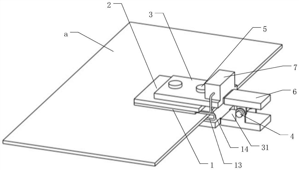
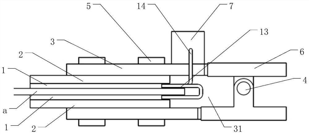
[0023] The following is attached Figures 1 to 4 The given examples further illustrate the specific implementation of a clamping temperature measuring device of the present invention. A clamping temperature measuring device of the present invention is not limited to the description of the following embodiments.

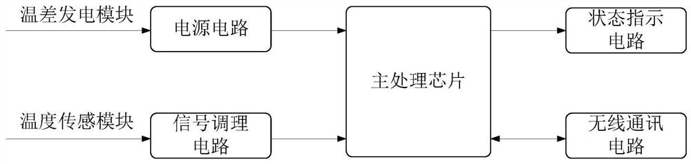
[0024] A clamping temperature measuring device, comprising a thermoelectric power generation module, a temperature sensing module, a controller module 7 and a clamping module; power supply, the temperature sensing module is used to sense the temperature of the power copper bar a and transmit the temperature signal to the controller module 7, the controller module 7 processes and converts the temperature signal transmitted by the temperature sensing module and transmits it to the external receiving terminal, The clamping module integrates the thermoelectric power generation module, the temperature sensing module and the controller module 7 and then connects them to th...


PUM


Abstract

A clamping temperature measuring device comprises a temperature difference power generation module, a temperature sensing module, a controller module and a clamping module. The temperature differencepower generation module is used for converting the temperature difference generated by heating of the power copper bar into electric energy to supply power to the controller module, and the temperature sensing module is used for sensing the temperature of the power copper bar and transmitting a temperature signal to the controller module. The controller module processes and converts temperature signals transmitted by the temperature sensing module and then transmits the temperature signals to an external receiving terminal, the clamping module integrates the temperature difference power generation module, the temperature sensing module and the controller module and then is connected with an electric power copper bar, and the clamping module is provided with a clamping cavity for the electric power copper bar to extend into. The thermoelectric power generation module and the temperature sensing module are located in the clamping cavity and fixed to the surface of the power copper bar under the action of the clamping module. The clamping temperature measuring device is not affected by the service life of the battery, the assembling process is simple, and operation is facilitated.

Description

technical field [0001] The invention relates to a circuit breaker temperature state detection device, in particular to a clamping temperature measurement device. Background technique [0002] In the low-voltage complete cabinet box, the local temperature of the power copper bar is often too high due to long-term overload operation or loose connection with the power equipment, which causes the local temperature of the power copper bar to be too high. Therefore, it is necessary to monitor its temperature in real time in order to detect its heating problem in advance. [0003] At present, intelligent temperature measuring devices are usually used to monitor the power copper bars, but the existing intelligent temperature measuring devices usually need to be powered by batteries or sensed by current transformers. These two power supply methods have their own defects. The battery-powered temperature measuring device is affected by the battery life. Once the battery life is approa...

Claims


Application Information

Patent Timeline
Patent Type & Authority Applications(China)
IPC IPC(8): G01K7/01G01K1/14G01K1/024H02N11/00
CPCG01K1/024G01K1/14G01K7/01H02N11/002
Inventor 胡应龙甘新华刘海蕊刘彬
Owner ZHEJIANG CHINT ELECTRIC CO LTD
Why Eureka
Try Eureka