Fuel cell system and humidity control method thereof

A fuel cell system and humidity control technology, applied in fuel cells, circuits, electrical components, etc., can solve problems such as increasing air temperature, increasing the difficulty of air compressor compression, and reducing air density.

Pending Publication Date: 2021-01-12
风氢扬氢能科技(上海)有限公司
View PDF0 Cites 10 Cited by
  • Summary
  • Abstract
  • Description
  • Claims
  • Application Information

AI Technical Summary

Problems solved by technology

However, discharging hydrogen into the air inlet will increase the temperature of the air at the air inlet, reduce the density of the air, increase...

Method used


Image

  • Fuel cell system and humidity control method thereof

Examples


Embodiment Construction

[0030] One of the cores of the present invention is to provide a fuel cell system to achieve the purpose of increasing the humidity of the air and moisture inside the stack and reducing the internal resistance of the stack.

[0031] Another core of the present invention is to provide a humidity control method based on the above-mentioned fuel cell system.

[0032] The following will clearly and completely describe the technical solutions in the embodiments of the present invention with reference to the accompanying drawings in the embodiments of the present invention. Obviously, the described embodiments are only some, not all, embodiments of the present invention. Based on the embodiments of the present invention, all other embodiments obtained by persons of ordinary skill in the art without making creative efforts belong to the protection scope of the present invention.

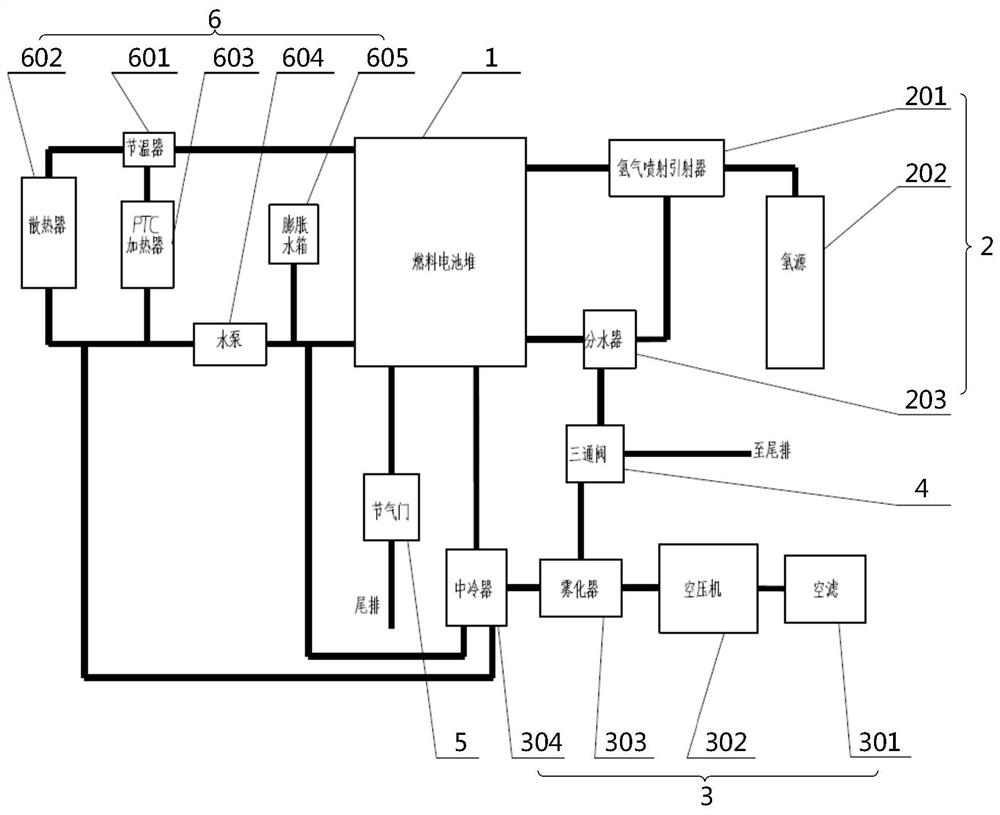
[0033] see figure 1 , figure 1 Schematic diagram of the structure of the fuel cell system provided by ...


PUM


Abstract

The invention relates to a fuel cell system and a humidity control method thereof. The fuel cell system comprises a fuel cell stack, a hydrogen loop and an air loop, the hydrogen loop comprises a hydrogen circulating device and a water segregator, and a hydrogen source is connected with a hydrogen inlet of the fuel cell stack through the hydrogen circulating device; a gas inlet of the water distributor is connected with a hydrogen outlet of the fuel cell stack, and a gas outlet of the water distributor is connected with the hydrogen circulating device; the air loop comprises an air filter, anair compressor, an atomizer and an intercooler which are sequentially connected in series, an outlet of the intercooler is connected to an air inlet of the fuel cell stack, and a water outlet of the water distributor is connected with the atomizer; according to the fuel cell system, the atomizer is arranged at the rear end of the air compressor of the air loop, moisture discharged by the anode ofthe galvanic pile can be added into the air in time to humidify the galvanic pile, an external water source is not needed, and therefore the purposes of increasing the humidity of the air and the moisture in the galvanic pile and reducing the internal resistance of the galvanic pile are achieved.

Description

technical field [0001] The invention relates to the technical field of fuel cells, in particular to a fuel cell system and a humidity control method thereof. Background technique [0002] At present, the membrane tube humidifier used in the fuel cell system on the market can effectively solve the problem of air humidification. Humidity will be subject to certain restrictions. At present, the humidifiers on the market can achieve a minimum dew point temperature of 15°C. When the operating temperature of the stack is 75°C and the temperature difference of the stack is within 10°C, the relative humidity of air humidification can reach about 50%, which can be lowered. Adjustment, but can not achieve a larger humidification ratio, and with the increase of operating temperature of the stack, the relative humidity of air humidification further decreases, which is not conducive to the internal reaction of the stack. [0003] A fuel cell system humidification solution is to pass pa...

Claims


Application Information

Patent Timeline
IPC IPC(8): H01M8/04828H01M8/04119
CPCH01M8/04126H01M8/04835Y02E60/50
Inventor 宋文帅田杰安韦熠
Owner 风氢扬氢能科技(上海)有限公司
Why Eureka
Try Eureka