Eureka AIR delivers breakthrough ideas for toughest innovation challenges, trusted by R&D personnel around the world.

Air film hole positioning tool and machining method thereof and air film hole machining and detecting method

A technology for positioning tooling and detection method, applied in electric processing equipment, metal processing equipment, accessories and other directions, can solve the problems of reducing the service life of turbine engine, affecting the cooling effect of turbine blades, low positioning accuracy of electrode wire, etc., to improve cooling effect, improve the processing quality, reduce the effect of hole position error

Inactive Publication Date: 2021-01-15
成都和鸿科技股份有限公司
View PDF11 Cites 2 Cited by
  • Summary
  • Abstract
  • Description
  • Claims
  • Application Information

AI Technical Summary

Problems solved by technology

[0003] However, at present, the processing of air film holes generally adopts electric spark drilling. When using electrode wire to drill holes, the positioning of the electrode wire, that is, the position of the air film hole on the blade, depends on the naked eye. This manual positioning method, the electrode wire The positioning accuracy is low, the hole position error of the air film hole is large, the production efficiency is low, the cooling effect of the turbine blade is affected, and the service life of the turbine engine is reduced

Method used


Image

  • Air film hole positioning tool and machining method thereof and air film hole machining and detecting method
  • Air film hole positioning tool and machining method thereof and air film hole machining and detecting method
  • Air film hole positioning tool and machining method thereof and air film hole machining and detecting method

Examples


Embodiment Construction

[0029] In order to make the purpose, technical solutions and advantages of the embodiments of the present invention clearer, the technical solutions in the embodiments of the present invention will be clearly and completely described below in conjunction with the drawings in the embodiments of the present invention. Obviously, the described embodiments It is a part of embodiments of the present invention, but not all embodiments. The components of the embodiments of the invention generally described and illustrated in the figures herein may be arranged and designed in a variety of different configurations.

[0030] Accordingly, the following detailed description of the embodiments of the invention provided in the accompanying drawings is not intended to limit the scope of the claimed invention, but merely represents selected embodiments of the invention. Based on the embodiments of the present invention, all other embodiments obtained by persons of ordinary skill in the art wi...


PUM


Abstract

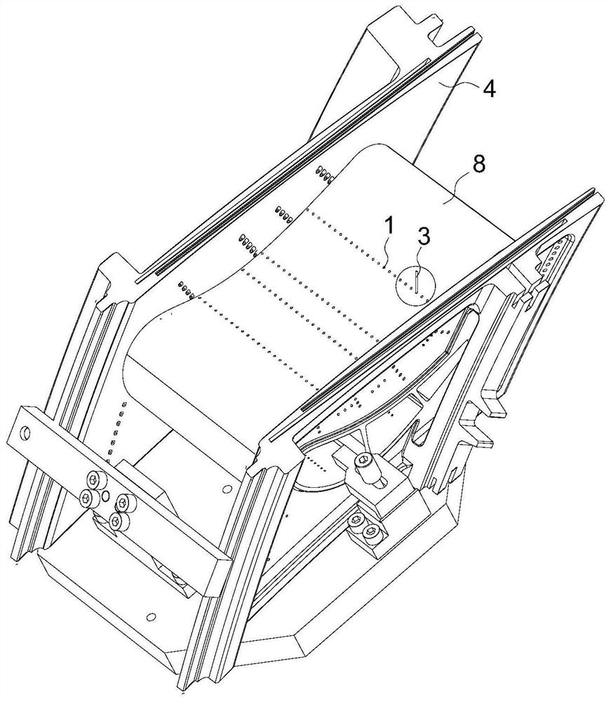
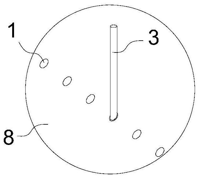
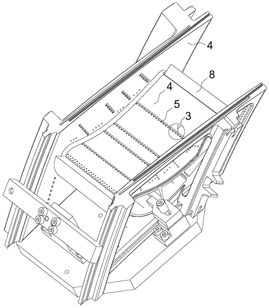
The invention discloses an air film hole positioning tool, and the air film hole positioning tool is used for electrosparking air film holes of turbine blades and comprises a positioning part used forclamping blade bodies of the turbine blades, and guide holes used for an electrode wire to penetrate through are formed in the positioning part in a penetrating manner. According to the air film holepositioning tool, the position precision of the air film holes can be improved, the hole position errors of the air film holes are reduced, the production efficiency is improved, and the cooling effect of turbine blades is improved.

Description

technical field [0001] The invention relates to the technical field of turbine blade processing, in particular to a gas film hole positioning tool and a processing method thereof, and a gas film hole processing and detection method. Background technique [0002] Turbine blades are an important component of the turbine section in a gas turbine engine. The high-speed rotating blades are responsible for drawing high-temperature and high-pressure air into the burner to maintain the engine's work. Turbine blades generally bear greater working stress and higher working temperature, and the changes of stress and temperature are frequent and severe. Moreover, in order to improve turbine efficiency, the surface shape of turbine blades is usually designed as a twisted variable-section surface. complex. In order to cool the turbine blades and prolong the service life of the turbine blades, air film holes are arranged in the turbine blades. [0003] However, at present, the processin...

Claims


Application Information

Patent Timeline
Patent Type & Authority Applications(China)
IPC IPC(8): B23H7/02B23H9/14B23H11/00F01D5/18
CPCB23H7/02B23H9/14B23H11/00F01D5/186
Inventor 张爱民徐培江郑珂郭志强李枚芬
Owner 成都和鸿科技股份有限公司
Why Eureka
Eureka Blog
Learn More