
Friction welding device with preheating function

A friction welding, functional technology, applied in the field of friction welding, can solve the problems of inability to preheat and fix operation, cumbersome and other problems

Active Publication Date: 2021-01-15
湖南坤鼎数控科技有限公司
View PDF11 Cites 7 Cited by
  • Summary
  • Abstract
  • Description
  • Claims
  • Application Information

AI Technical Summary

Problems solved by technology

[0005] The purpose of the present invention is to provide a friction welding device with a preheating function in order to solve the problems of inability to preheat and complicated fixing operations

Method used


Image

  • Friction welding device with preheating function
  • Friction welding device with preheating function
  • Friction welding device with preheating function

Examples


Embodiment Construction

[0028] The technical solutions in the embodiments of the present invention will be clearly and completely described below in conjunction with the accompanying drawings in the embodiments of the present invention. Obviously, the described embodiments are only some of the embodiments of the present invention, not all of them. Based on the embodiments of the present invention, all other embodiments obtained by persons of ordinary skill in the art without creative work all belong to the protection scope of the present invention.

[0029]In the description of the present invention, it should be noted that the terms "center", "upper", "lower", "left", "right", "vertical", "horizontal", "inner", "outer" etc. The indicated orientation or positional relationship is based on the orientation or positional relationship shown in the drawings, and is only for the convenience of describing the present invention and simplifying the description, rather than indicating or implying that the refer...


PUM


Abstract

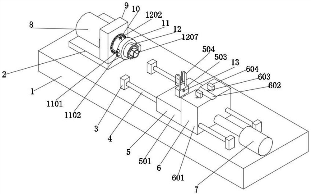
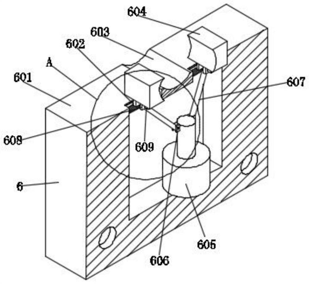
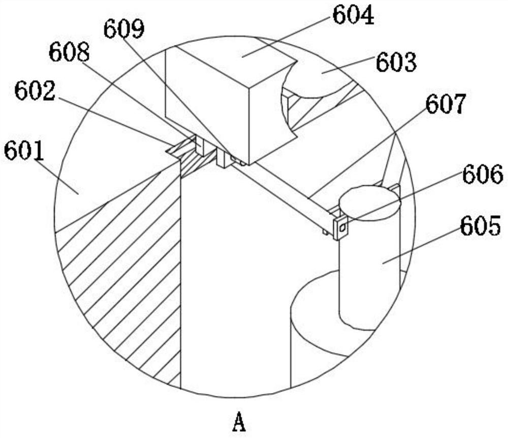
The invention discloses a friction welding device with a preheating function, and relates to the technical field of friction welding. The friction welding device with the preheating function comprisesa base, wherein a fixing table is arranged at the top end of the base; a motor and a fixing block are arranged at the top end of the fixing table; the fixing block is close to the position of the output end of the motor; and the inner wall of the fixing block is sleeved with a bearing. According to the invention, the preheating function is achieved through arrangement for a preheating table, a second electric push rod, a preheating box, an induction coil, a connecting hole, a telescopic block, a spring and a transformer, an alternating current is led in through the induction coil, and therefore an alternating magnetic field is formed, and materials to be welded generate vortexes to be heated through the magnetic field; and the height of the induction coil can be adjusted through the second electric push rod, the induction coil is configured to be in a semi-arc shape, and the materials can be conveniently placed and taken out through the semi-arc shape.

Description

technical field [0001] The invention relates to the technical field of friction welding, in particular to a friction welding device with a preheating function. Background technique [0002] Friction welding refers to the method of using the heat generated by the friction of the contact surface of the workpiece as the heat source to cause the workpiece to undergo plastic deformation under pressure. Under the action of pressure, it is under the action of constant or increasing pressure and torque. The relative movement between the contact end surfaces generates frictional heat and plastic deformation heat on the friction surface and its surrounding area, so that the temperature of the nearby area rises to a temperature range close to but generally lower than the melting point, and the deformation resistance of the material decreases and the plasticity improves. The oxide film on the interface is broken, and under the action of the upsetting pressure, the material undergoes pla...

Claims


Application Information

Patent Timeline
Patent Type & Authority Applications(China)
IPC IPC(8): B23K20/12B23K20/26B23K37/04
CPCB23K20/122B23K20/26B23K37/0435
Inventor 张新胜雷勋发吴靖凡
Owner 湖南坤鼎数控科技有限公司
Learn More