Eureka AIR delivers breakthrough ideas for toughest innovation challenges, trusted by R&D personnel around the world.

Plate shearing machine for metal processing

A metal processing and shearing machine technology, applied in metal processing, metal processing machinery parts, metal processing equipment, etc., can solve the problems of not installing shock absorbing devices, delaying production plans, and not being able to play the role of shock absorption, etc., to achieve high Practical value, the effect of solving poor product quality

Inactive Publication Date: 2021-01-15
马鞍山维拓商贸有限公司
View PDF0 Cites 0 Cited by
  • Summary
  • Abstract
  • Description
  • Claims
  • Application Information

AI Technical Summary

Problems solved by technology

However, the shearing machines currently on the market are not equipped with shock absorbing devices, which cannot play a role in shock absorption, and most metal processing shearing machines have general feeding devices, and most of the feeding and loading are carried out by manual cutting. The safety of manual handling and cutting is low. At the same time, it will be very time-consuming and labor-intensive, which may delay the production plan and increase the production cost. Therefore, we have improved this and proposed a shearing machine for metal processing.

Method used


Image

  • Plate shearing machine for metal processing
  • Plate shearing machine for metal processing
  • Plate shearing machine for metal processing

Examples


Embodiment

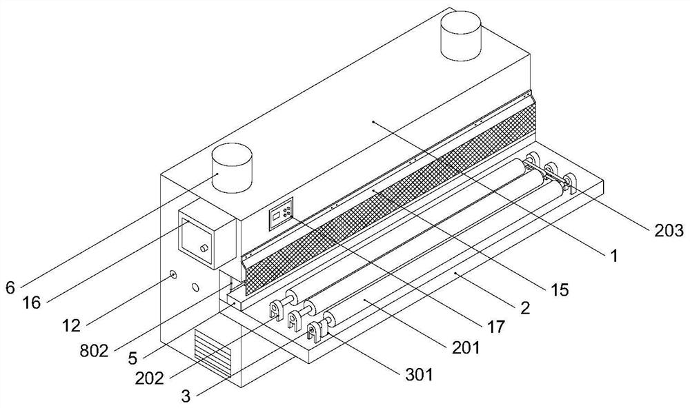
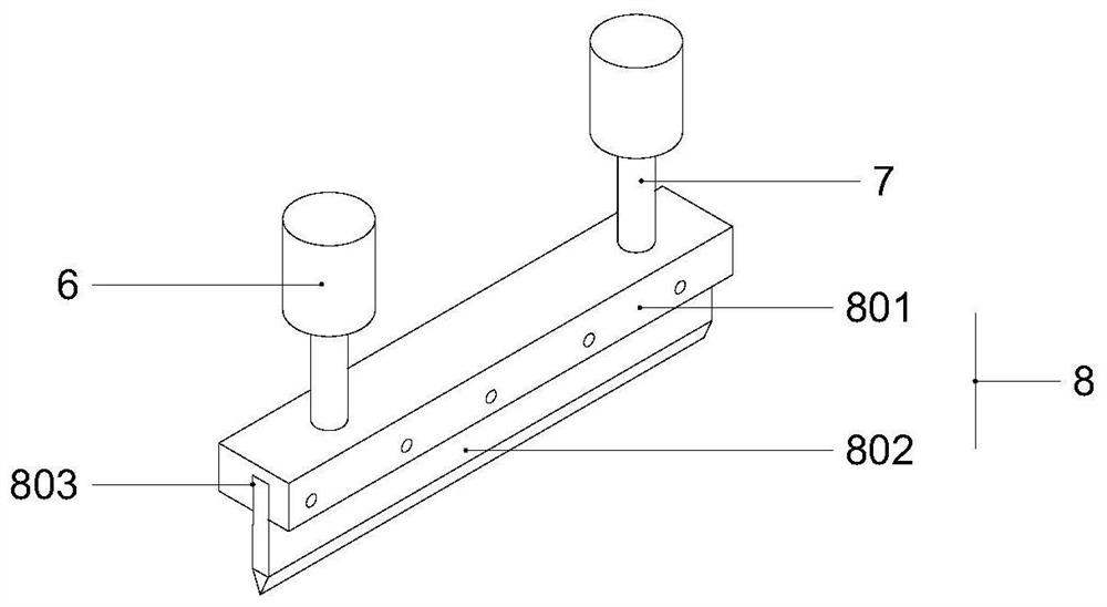
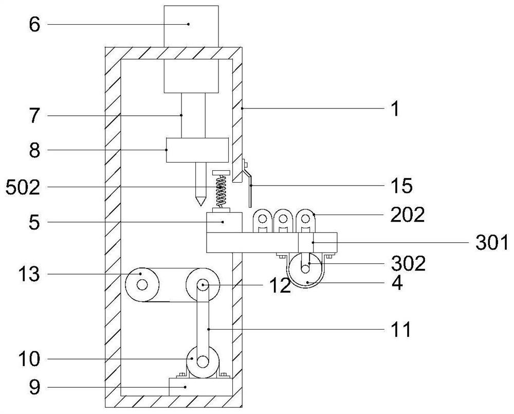
[0021] Example: such as Figure 1-4 As shown, a metal shearing machine of the present invention includes a body 1, a transport plate 2 is fixedly installed on one side of the body 1, a first transport wheel 201 is fixedly installed on the top side of the transport plate 2, and the first transport wheel 201- The first rotating shaft 3 is arranged on one side, the first motor 4 is connected to one side of the first rotating shaft 3, the shock absorbing plate 5 is fixedly installed on the other side of the top of the transport plate 2, the cylinder 6 is fixedly installed on the top of the body 1, and the bottom of the cylinder 6 The telescopic rod 7 is fixedly installed at the end, and the bottom end of the telescopic rod 7 is fixedly connected with a cutting device 8, the cutting device 8 is composed of a cutting block 801 and a cutting blade 802, the bottom end of the body 1 is fixedly installed by a fixed block 9, and the top of the fixed block 9 is fixedly installed There is ...


PUM


Abstract

The invention provides a plate shearing machine for metal processing. The plate shearing machine comprises a machine body, wherein one side of the machine body is fixedly provided with a conveying plate; one side of the top end of the conveying plate is fixedly provided with a first conveying wheel; one side of the first conveying wheel is provided with a first rotating shaft; one side of the first rotating shaft is connected with a first motor; the other side of the top end of the conveying plate is fixedly provided with a damping plate; the top end of the machine body is fixedly provided with an air cylinder; the bottom end of the air cylinder is fixedly provided with a telescopic rod; the bottom end of the telescopic rod is fixedly connected with a cutting device; the cutting device consists of a cutting block and a cutting blade; the bottom end of the machine body is fixedly provided with a fixing block; the top end of the fixing block is fixedly provided with a second motor; one side of the second motor is fixedly connected with a first belt; and one end of the first belt is fixedly connected with a second rotating shaft. The plate shearing machine for metal processing can effectively solve the problems of poor product quality, low manual carrying and cutting safety and low manual carrying working efficiency caused by excessive vibration frequency in the cutting process, and has high practical value.

Description

technical field [0001] The invention relates to the technical field of metal processing, in particular to a shearing machine for metal processing. Background technique [0002] Metal processing is indispensable in modern society. Metal processing is to process metal materials into various metal objects. Among them, shearing machines are very common in metal processing. Shearing machines can apply shear to metal sheets of various thicknesses. Cutting force, so that the plate is broken and separated according to the required size. [0003] Shearing machines for metal processing are widely used in various industries, and are suitable for providing special machinery and complete sets of equipment required by aviation, light industry, metallurgy, shipbuilding, automobile, electric power, electrical appliances and other industries. However, the shearing machines currently on the market are not equipped with shock absorbing devices, which cannot play a role in shock absorption, an...

Claims


Application Information

Patent Timeline
Patent Type & Authority Applications(China)
IPC IPC(8): B23Q7/05B23Q11/08B23Q11/00
CPCB23Q7/055B23Q11/00B23Q11/0032B23Q11/0042B23Q11/08
Inventor 李波宋大名
Owner 马鞍山维拓商贸有限公司
Why Eureka
Eureka Blog
Learn More