Anti-blocking three-grid septic tank capable of promoting efficient fermentation

A technology for septic tanks and septic tanks, applied in biological sludge treatment and other directions, can solve problems such as difficulty in cleaning feces, clogging, and affecting the continued decomposition of fecal residues, and achieve the effects of facilitating cleaning, improving safety and sealing.

Inactive Publication Date: 2021-01-15
叶广丽
View PDF0 Cites 0 Cited by
  • Summary
  • Abstract
  • Description
  • Claims
  • Application Information

AI Technical Summary

Problems solved by technology

[0003] However, after the existing three-compartment septic tank has been used for a long time, the dung will continue to settle downwards, compacting and agglomerating the dung at the bottom, which will not only affect the continued decomposition of the dung, but also easily cause blockage, resulting in the inability of the hydrate to flow. To the next pool, it also brings difficulties to clear the manure. Therefore, the present invention proposes a kind of anti-blocking three-compartment septic tank that can solve the above problems and can promote high-efficiency fermentation.

Method used


Image

  • Anti-blocking three-grid septic tank capable of promoting efficient fermentation
  • Anti-blocking three-grid septic tank capable of promoting efficient fermentation
  • Anti-blocking three-grid septic tank capable of promoting efficient fermentation

Examples


Embodiment 2

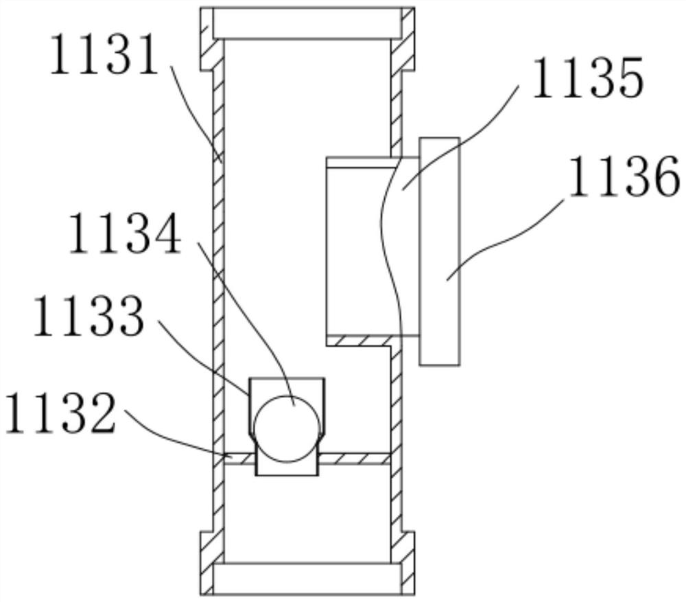
[0038] On the basis of Example 1, as an optional situation, please refer to figure 1 and image 3 , the exhaust assembly 113 includes a connecting pipe 1131 and a side pipe 1135, the connecting pipe 1131 is arranged in the middle of the exhaust pipe 112, the lower part of the connecting pipe 1131 is provided with a baffle 1132, and the middle of the connecting pipe 1131 is provided with an exhaust funnel penetrating through the baffle 1132 1133, a lightweight ball 1134 is movable in the exhaust funnel 1133, a side pipe 1135 is connected to the side wall of the middle part of the connecting pipe 1131, and a sealing cover 1136 is installed on the end of the side pipe 1135 away from the connecting pipe 1131, anaerobic fermentation in the first pool 110 After the generated gas gathers under the baffle plate 1132 of the connecting pipe 1131 to generate positive pressure, the light ball 1134 in the exhaust bucket 1133 is lifted up for exhaust. After the exhaust is completed, the lig...

Embodiment 3

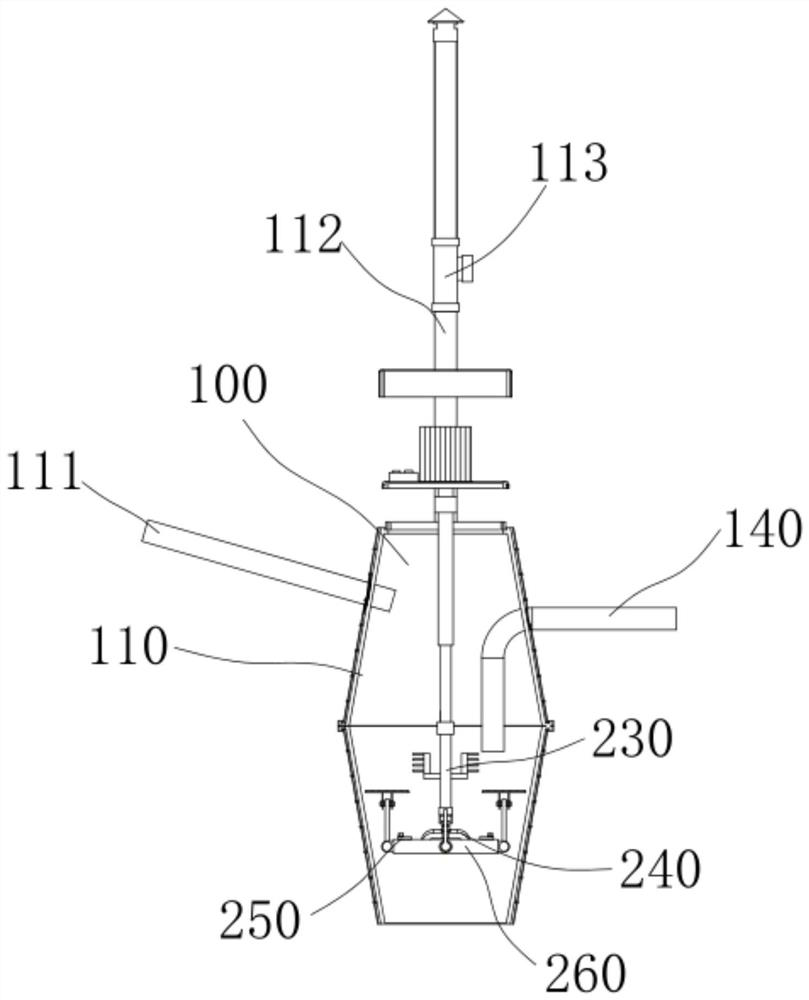
[0040] On the basis of Example 1, as an optional situation, please refer to figure 1 , Figure 7 and Figure 8 , the card shaft 251 is movably connected with the swing frame 260 through the moving plate 250, and the two sides of the lower end of the moving plate 250 are provided with sliders 254. Matching fixing holes 252 are provided on the frame 260 and connected by bolts 253 . A slot 263 is provided on the inner wall of the limiting sleeve 262 , a pivotable rotating cover 273 is provided at the inner end of the limiting shaft 270 , and a strip 274 matching the slot 263 is provided on the outer side of the rotating cover 273 . The moving plate 250 can move along the chute 261 on the swing frame 260 through the slider 254. When the swing frame 260 and the swing arm 240 are connected, the moving plate 250 is moved to the side close to the swing arm 240 in turn, so that the clamping shaft 251 moves to the The ferrule 241 is clipped, and screwed in the bolt 253 in the fixed h...


PUM


Abstract

The invention discloses an anti-blocking three-grid septic tank capable of promoting efficient fermentation. The septic tank comprises a septic tank body, the septic tank body comprises a first tank,a second tank and a third tank, an excrement inlet pipe is arranged on one side of the first tank, an exhaust pipe is arranged on the side wall of the upper portion of the first tank, an exhaust assembly is arranged in the middle of the exhaust pipe, the second tank is communicated with the first tank through a first excrement passing pipe, the second tank is communicated with the third tank through a second excrement passing pipe, sewage draining outlets are formed in the upper ends of the first tank, the second tank and the third tank, an openable isolation cover is arranged on each sewage draining outlet, a safety cover is arranged on the isolation cover, a motor is fixedly arranged on the isolation cover of the first tank, and the lower end of an electric telescopic rod is connected with a rotating shaft by a bottom coupling. Lifting rods at the left end and the right end of a swing frame drive lifting plates to vertically move in excrement residues, compacted, caked and hardened excrement residues are broken through a plurality of convex edges on the upper end face, further fermentation of excrement residues at the bottom of a first tank is promoted, the first excrement passing pipe is not prone to being blocked, and the excrement residues are convenient to clean.

Description

technical field [0001] The invention relates to the technical field of septic tanks, in particular to an anti-blocking three-compartment septic tank that can promote high-efficiency fermentation. Background technique [0002] The three-compartment septic tank is to carry out the collection and harmless treatment of feces in the same process. The principle is that the feces enter the first pool from the manure inlet, and the feces in the pool begin to ferment and decompose. Due to the different specific gravity, the feces can be naturally divided into the upper layer. The hydrate and the lower layer of dung, the upper layer of hydrate overflows to the second tank through the dung pipe, and the dung is retained in the first dung tank to continue fermentation, and the dung liquid flowing into the second tank is further fermented and decomposed. To obtain further detoxification, the fecal liquid flowing into the third pool is generally decomposed, and the germs and parasite eggs...

Claims


Application Information

Patent Timeline
IPC IPC(8): C02F11/04
CPCC02F11/04
Inventor 叶广丽
Owner 叶广丽
Why Eureka
Try Eureka