Capillary tube double-path triggering device for series gap and application thereof

A technology of triggering devices and series gaps, which is applied in measuring devices, circuit breaker testing, instruments, etc., can solve the problems of increasing the technical difficulty of gas gap breakdown triggering, and meet the needs of precise timing control and good ablation resistance , The effect of improving the efficiency of the test work

Active Publication Date: 2021-01-15
XI AN JIAOTONG UNIV
View PDF4 Cites 0 Cited by
  • Summary
  • Abstract
  • Description
  • Claims
  • Application Information

AI Technical Summary

Problems solved by technology

In particular, for applications with high voltage levels or simultaneous use of AC and DC power supplies, in order to ensure reliability, gas gaps often use double gaps in series, which further increases the technical difficulty of triggering gas gap breakdown

Method used


Image

  • Capillary tube double-path triggering device for series gap and application thereof
  • Capillary tube double-path triggering device for series gap and application thereof
  • Capillary tube double-path triggering device for series gap and application thereof

Examples


Embodiment 1

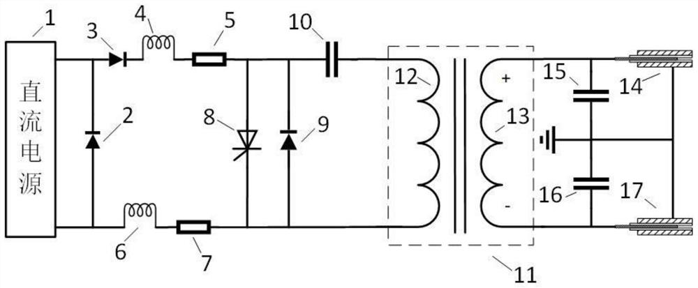
[0055] see figure 1 , the present embodiment is a capillary two-way trigger device for a series gap, including a pulse source, a single-gap capillary, and a voltage equalizing capacitor.

[0056] Pulse sources include pulse capacitors, DC power supplies, thyristors, freewheeling diodes, pulse transformers, protection inductors, protection resistors and protection diodes.

[0057] Wherein, the capacitance value of the pulse capacitor is 1 μF.

[0058] The DC power supply is connected in parallel to both ends of the pulse capacitor through a protection inductor and a protection resistor, and its output terminals are respectively connected in series and in parallel with protection diodes to form a pulse charging circuit together.

[0059] The pulse capacitor is connected in series with the parallel circuit of the thyristor and the freewheeling diode, and the primary side of the pulse transformer to form a pulse discharge circuit.

[0060] After receiving the pulse ignition sign...

Embodiment 2

[0067] see figure 1 , the present embodiment is a capillary two-way trigger device for a series gap, including a pulse source, a single-gap capillary, and a voltage equalizing capacitor.

[0068] Pulse sources include pulse capacitors, DC power supplies, thyristors, freewheeling diodes, pulse transformers, protection inductors, protection resistors and protection diodes.

[0069] Wherein, the capacitance value of the pulse capacitor is 2 μF.

[0070] The DC power supply is connected in parallel to both ends of the pulse capacitor through a protection inductor and a protection resistor, and its output terminals are respectively connected in series and in parallel with protection diodes to form a pulse charging circuit together.

[0071] The pulse capacitor is connected in series with the parallel circuit of the thyristor and the freewheeling diode, and the primary side of the pulse transformer to form a pulse discharge circuit. After receiving the pulse ignition signal, the thy...

Embodiment 3

[0078] see figure 1 , the present embodiment is a capillary two-way trigger device for a series gap, including a pulse source, a single-gap capillary, and a voltage equalizing capacitor.


PUM


Abstract

The invention discloses a capillary tube double-circuit triggering device for series gaps and an application thereof, single-gap capillary tubes are respectively embedded in corresponding gaps and arerespectively connected with a pulse transformer secondary side of a pulse transformer through corresponding voltage-sharing capacitors, a pulse transformer primary side is connected with a direct-current power supply through a pulse discharge loop, and the direct-current power supply is connected with a direct-current power supply; an output end of the direct-current power supply is serially connected with the pulse charging loop. The two-way single-gap capillary tube is adopted for discharging, the technology is advanced, the structure is simple, the control performance is excellent, and theseries gap can be effectively, rapidly, accurately and reliably conducted.

Description

technical field [0001] The invention belongs to the technical field of pulse power, and in particular relates to a capillary two-way trigger device for series gaps and its application. Background technique [0002] With the continuous improvement of high-voltage switch manufacturing level, direct test has been difficult to meet the test requirements of high-voltage large-capacity circuit breakers. At present, more economical and effective synthetic test methods are used at home and abroad to test high-voltage large-capacity circuit breakers in the form of joint operation of low-voltage current source and high-voltage voltage source. Among them, the current source voltage is only a fraction of the rated voltage of the circuit breaker, and special arc extension measures need to be taken to prevent the test product from prematurely extinguishing the arc compared with the direct test condition, so that the circuit breaker has Same arcing time range as at rated voltage. [0003...

Claims


Application Information

Patent Timeline
Patent Type & Authority Applications(China)
IPC IPC(8): G01R31/327
CPCG01R31/3274
Inventor 杨兰均魏鹏曹博韩佳一路志建
Owner XI AN JIAOTONG UNIV
Why Eureka
Try Eureka