
System and method for abating non-required order influence of diffractive optical device

A diffractive optics and optical device technology, applied in the field of optics, can solve the problem of inability to effectively reduce the effects of undesired orders, and achieve the effect of reducing adverse effects and increasing the number of split beams

Active Publication Date: 2021-01-15
HUAZHONG UNIV OF SCI & TECH
View PDF11 Cites 0 Cited by
  • Summary
  • Abstract
  • Description
  • Claims
  • Application Information

AI Technical Summary

Problems solved by technology

[0006] In view of the above defects or improvement needs of the prior art, the present invention provides a system and method for reducing the influence of the unwanted orders of the diffractive optical device. When the light field distribution of the desired order overlaps with the light field distribution of the undesired order, the technical problem that the influence of the undesired order cannot be effectively reduced

Method used


Image

  • System and method for abating non-required order influence of diffractive optical device
  • System and method for abating non-required order influence of diffractive optical device
  • System and method for abating non-required order influence of diffractive optical device

Examples


Embodiment 1

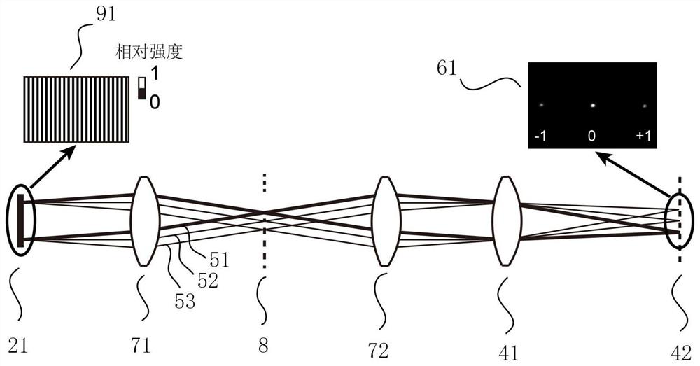
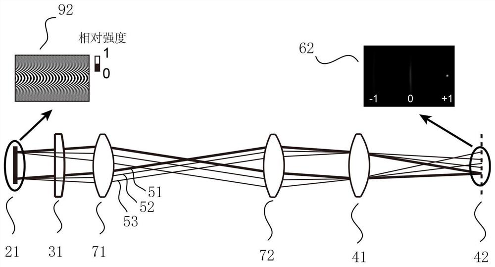
[0037] A system for reducing the effects of undesired orders in diffractive optics, such as figure 1 As shown, it includes: a light generator 1, a diffractive optical device 2 and a beam focusing device 4 placed in sequence along the direction of the light path, and an aberration optic placed between the image square focal plane of the light generator 1 and the beam focusing device 4 Device 3; Specifically, in this embodiment, the aberration optical device 3 is placed between the diffractive optical device 2 and the beam focusing device 4;

[0038] Wherein, the light generator 1 is used to provide a light source; the light generator 1 can be a laser, a light emitting diode, a mercury lamp, a halogen lamp, etc.;

[0039] The aberration optical device 3 is used to increase the first optical aberration in the optical path to degrade the beam quality in the optical path; specifically, the aberration optical device 3 can be any optical device that can increase the aberration in the...

Embodiment 2

[0057] A method for reducing the effects of unwanted orders in a diffractive optical device, comprising the steps of:

[0058] S1. Adding the first optical aberration in the optical path where the diffractive optical device is located degrades the beam quality; specifically, the method of increasing the first optical aberration in the optical path includes: using a cylindrical lens to generate astigmatism; or, based on a deformable The irregular reflective surface of the mirror introduces aberrations; or, making the beam incident on the edge of the lens, introduces astigmatism and coma. It should be noted that the first optical aberration is different from the aberration generated by optical devices and optical elements during normal use, and is the aberration added to the optical path by intentionally placing an aberration optical device in the optical path.

[0059] S2. Based on the diffractive optical device, the beam is wavefront modulated to obtain the outgoing light; the...


PUM


Abstract

The invention discloses a system and a method for eliminating non-required order influence of a diffractive optical device, and belong to the field of optics. The system comprises a light generator, the diffractive optical device and a light beam focusing device which are sequentially arranged along a light path direction, and an aberration optical device arranged between the light generator and an image space focal plane of the light beam focusing device. According to the system, a first optical aberration is increased in the optical path through the aberration optical device so that the quality of a light beam in the optical path is degraded; and in the process of carrying out wavefront modulation on the incident light beam by adopting the diffractive optical device, a second optical aberration which is mutually compensated with the first optical aberration is introduced to the light beam of the required order so that the light field distribution of the required order is kept in a clear state, and the light field distribution of the non-required order is degraded by the increased first aberration. Therefore, the influence of the non-required order is effectively reduced.

Description

technical field [0001] The invention belongs to the field of optics, and more specifically relates to a system and method for reducing the influence of unwanted orders of a diffractive optical device. Background technique [0002] Diffractive optical devices are widely used in the field of optics, such as laser processing, biological microscopic imaging, information optical storage, etc. Commonly used diffractive optical devices include gratings, acousto-optic deflectors, spatial light modulators (spatial lightmodulators, SLMs), digital micromirror devices (digital micromirror devices, DMDs), metasurface materials, and diffractive optical elements (diffractive optical elements, DOEs). Wait. The diffractive optical element can modulate the optical parameters (phase, amplitude) of the wavefront of the incident light beam, so as to change the corresponding optical parameters of the wavefront of the outgoing light. At the same time, the magnitude and spatial distribution of th...

Claims


Application Information

Patent Timeline
IPC IPC(8): G02B27/00G02B27/09G02B27/42
CPCG02B27/4205G02B27/0025G02B27/0037G02B27/0944G02B27/0966
Inventor 曾绍群王雨胡庆磊吕晓华
Owner HUAZHONG UNIV OF SCI & TECH
Learn More