Rapid analysis system for composite material nail loads

Inactive Publication Date: 2021-01-15
NORTHWESTERN POLYTECHNICAL UNIV
View PDF4 Cites 2 Cited by
  • Summary
  • Abstract
  • Description
  • Claims
  • Application Information

AI Technical Summary

Problems solved by technology

When the number of models to be processed is large, there is often a large workload, and some misoperations will inevitably occur due to human factors, which will inevitably affect the accuracy of calculations

Method used


Image

  • Rapid analysis system for composite material nail loads
  • Rapid analysis system for composite material nail loads
  • Rapid analysis system for composite material nail loads

Examples


Embodiment

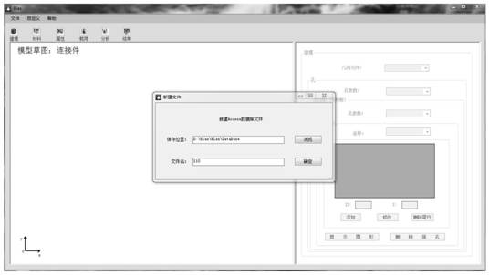
[0053] (1) Create a new data file named "110", as attached Image 6 shown;

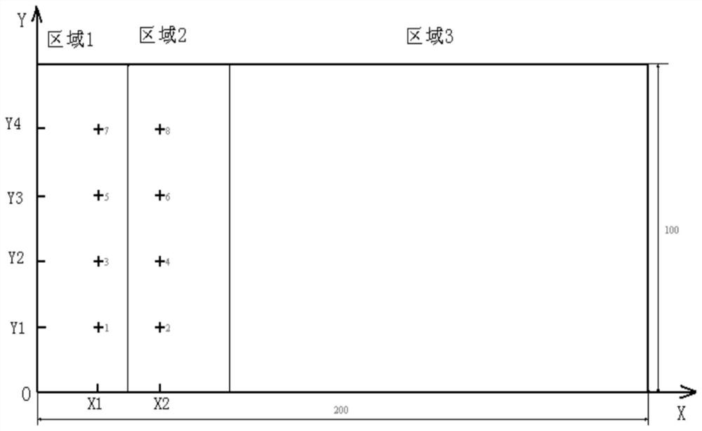
[0054] (2) Input the parameters of the composite material plate. The width and length of each area are attached Figure 7 As shown, set the number of holes and the X and Y coordinates as attached Figure 8 As shown, set the diameter of each hole as attached Figure 9 As shown, the completed composite board is shown in the attached Figure 10 shown;

[0055] (3) Select the lap joint type, and input parameters such as edge distance and end distance of the lap joint plate, as attached Figure 11 shown;

[0056] (4) Establish the material parameters of composite boards, lap joints, screws, etc. The material parameters of composite boards are as attached Figure 12 shown;

[0057] (5) Establish parameters such as composite plate properties, metal plate properties, and beam unit properties in each area. The properties of composite plate units are as follows: Figure 13 shown;

[0058] (6) Assign t...


PUM


Abstract

The invention relates to the technical field of composite material mechanical connection structure load calculation, in particular to a rapid analysis system for composite material nail loads which directly calls PATRAN to perform modeling according to structure geometrical parameters, material parameters, attribute parameters, load parameters and the like input by a user and calls NASTRAN to perform calculation. Load size and the distribution proportion of each nail can be obtained. The load distribution proportion of the composite material nailing structure can be rapidly calculated, the complex modeling and analysis process is removed. The two-dimensional modeling method of mechanical connection is improved, the calculation accuracy is improved, and the modeling time is greatly saved.

Description

technical field [0001] The invention relates to the technical field of load calculation of composite material mechanical connection structures, in particular to a fast analysis system for composite material nail loading. Background technique [0002] Composite laminates have been increasingly used in aircraft structures due to their high specific strength, specific stiffness, and corrosion resistance. This results in a large number of mechanical connections between the composite structure and its metal structure. Among them, the bolt connection has become the most important mechanical connection method due to its advantages of high load bearing, convenient loading and unloading, and very reliable. Due to the stress concentration at the edge of the hole and the large transfer load, the composite bolt connection has become the weakest link in the structure and is prone to damage. Therefore, it is of great significance to analyze the load distribution at the joint structure o...

Claims


Application Information

Patent Timeline
Patent Type & Authority Applications(China)
IPC IPC(8): G06F30/17G06F111/10G06F113/26
CPCG06F30/17G06F2113/26G06F2111/10
Inventor 黄河源侯赤王东王文智李冰赵美英周银华
Owner NORTHWESTERN POLYTECHNICAL UNIV
Why Eureka
Try Eureka