Waveguide structure linear polarization complementary source antenna based on 3D printing technology

A waveguide structure and 3D printing technology, which is applied in the structural form of radiation elements, antenna grounding switch structure connection, additive processing, etc., can solve the complex structure of complementary source antennas in the microwave frequency band, insufficient mechanical properties of metal waveguide structures, and sensitivity to processing errors, etc. problems, to achieve the effect of solving performance sensitivity problems, light weight, and stable gain

Pending Publication Date: 2021-01-15
SOUTH CHINA UNIV OF TECH
View PDF0 Cites 0 Cited by
  • Summary
  • Abstract
  • Description
  • Claims
  • Application Information

AI Technical Summary

Problems solved by technology

[0007] The purpose of the present invention is to solve the problem of the complex structure of the traditional microwave frequency band complementary source antenna, the problem that the performance of the traditional microwave frequency band complementary source antenna is sensitive to processing errors due to post-processing, and the traditional microwave frequency band complementary source antenna due to the participation of metal structures. The problem of heavy weight and the problem of insufficient mechanical properties and easy deformation of the 3D printed metal waveguide structure

Method used


Image

  • Waveguide structure linear polarization complementary source antenna based on 3D printing technology
  • Waveguide structure linear polarization complementary source antenna based on 3D printing technology
  • Waveguide structure linear polarization complementary source antenna based on 3D printing technology

Examples


Embodiment

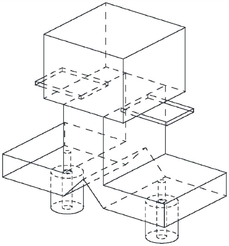
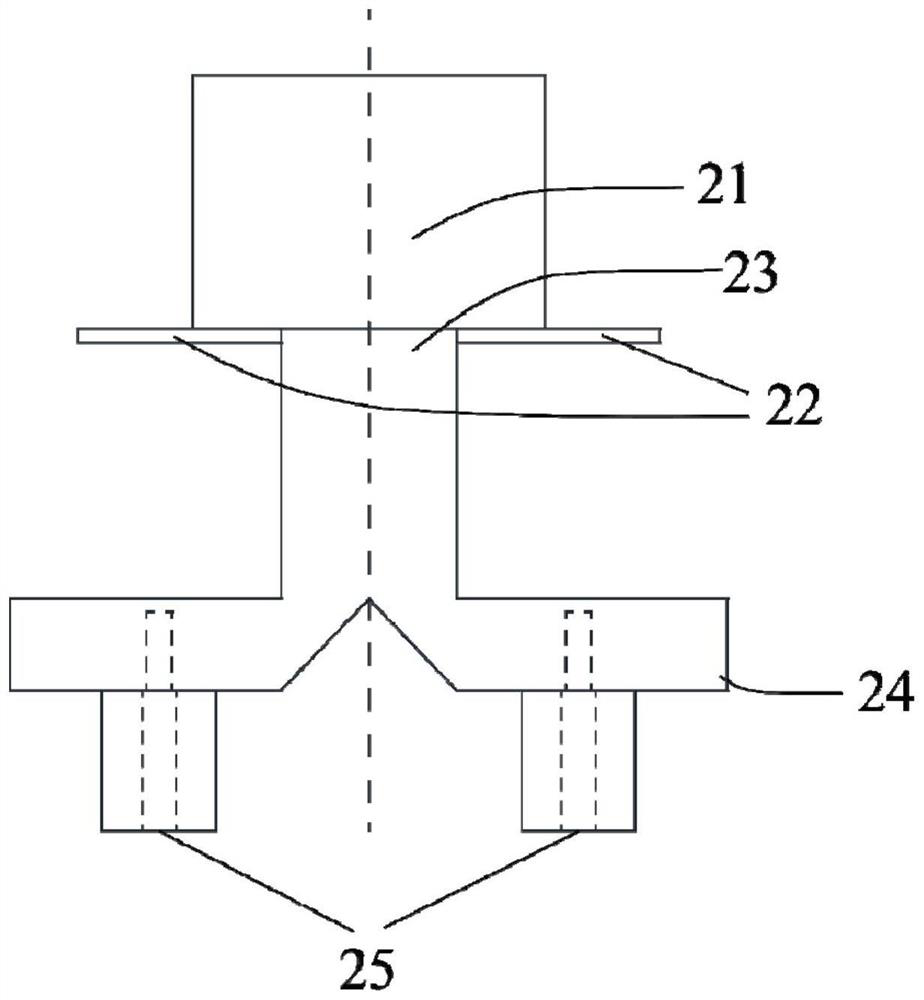
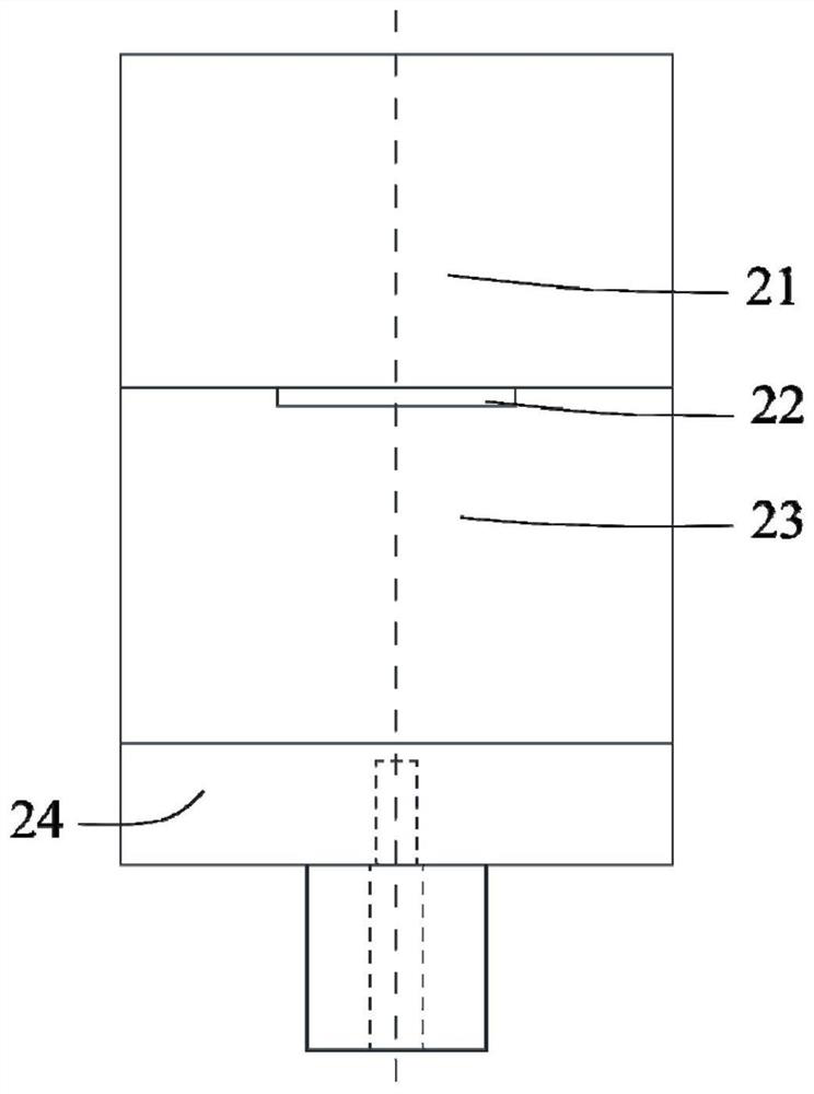
[0037] A waveguide structure linearly polarized complementary source antenna based on 3D printing technology, such as figure 1 , figure 2 , image 3 As shown, it includes a rectangular dielectric block 21, two rectangular dielectric sheets 22, TE 10 Mode rectangular opening waveguide 23, E-plane T-junction waveguide power divider 24 and two coaxial connectors 25;

[0038] Among them, the rectangular dielectric block 21 is located at the top of the antenna, and TE 10 Mode rectangular opening waveguides 23 are connected; TE 10 The E-plane T-junction waveguide power divider 24 is connected to the bottom of the mode rectangular opening waveguide 23; the structural parameters of the two rectangular dielectric sheets 22 are exactly the same, and the TE 10 The wide side of the mode rectangular opening waveguide 23 cross-section is symmetrically placed at the opening connected to the rectangular dielectric block 21, and the TE 10 The mode rectangular opening waveguide 23 is conn...


PUM


Abstract

The invention discloses a waveguide structure linear polarization complementary source antenna based on a 3D printing technology. The antenna comprises a rectangular dielectric block, two rectangulardielectric sheets, a TE10 mode rectangular open waveguide, an E-plane T-junction waveguide power divider and two coaxial connectors. The rectangular dielectric block is located at the uppermost part of the antenna and is connected with the TE10 mode rectangular open waveguide; the E-plane T-junction waveguide power divider is connected below the TE10 mode rectangular open waveguide; the two rectangular dielectric sheets have the same structural parameters, are attached to the wide edge of the cross section of the TE10 mode rectangular open waveguide, are symmetrically placed at the opening connected with the rectangular dielectric block and are connected with the TE10 mode rectangular open waveguide; and the lower part of the E-plane T-junction waveguide power divider is connected with twocoaxial connectors. The antenna provided by the invention effectively solves the problem of performance sensitivity of the traditional microwave frequency band complementary source antenna caused byerrors in later processing, and has the advantages of simple structure, easiness in processing, quick forming and light weight.

Description

technical field [0001] The invention relates to the technical field of antennas, in particular to a waveguide structure linearly polarized complementary source antenna based on 3D printing technology. Background technique [0002] 3D printing technology is a rapid prototyping technology for the purpose of building structures by orderly laminating, extruding, and sintering raw materials. Different from the traditional CNC process that processes objects by means of subtractive materials, 3D printing uses additive methods to build the required structure, which can largely avoid the waste of raw materials. Through 3D model files, 3D printing technology is capable of processing various complex and special-shaped structures, and has a very short processing cycle, which can greatly save manpower and material resources. At present, 3D printing technology has been applied in the field of antennas, such as transmission array and prism design using dielectric materials, horn antennas ...

Claims


Application Information

Patent Timeline
IPC IPC(8): H01Q1/36H01Q1/50B33Y80/00
CPCB33Y80/00H01Q1/36H01Q1/50
Inventor 马自龙张楚唯
Owner SOUTH CHINA UNIV OF TECH
Why Eureka
Try Eureka