
Bus charging control device, driver and bus charging control method thereof

A charge control method and charge control technology, which are applied to circuit devices, battery circuit devices, emergency protection circuit devices, etc., can solve problems such as difficult control, and achieve the effect of reducing the difficulty of suppression

Inactive Publication Date: 2021-01-15
GREE ELECTRIC APPLIANCES INC
View PDF14 Cites 0 Cited by
  • Summary
  • Abstract
  • Description
  • Claims
  • Application Information

AI Technical Summary

Problems solved by technology

[0005] The purpose of the present invention is to provide a bus charging control device, a driver and a bus charging control method thereof, to solve the problem that it is difficult to control the input current by using a PTC resistor in the front stage of the driver input circuit, so as to reduce the impact on the driver input circuit. The effect of the difficulty of suppressing the input current of the previous stage

Method used


Image

  • Bus charging control device, driver and bus charging control method thereof
  • Bus charging control device, driver and bus charging control method thereof
  • Bus charging control device, driver and bus charging control method thereof

Examples


Embodiment Construction

[0034]In order to make the purpose, technical solution and advantages of the present invention clearer, the technical solution of the present invention will be clearly and completely described below in conjunction with specific embodiments of the present invention and corresponding drawings. Apparently, the described embodiments are only some of the embodiments of the present invention, but not all of them. Based on the embodiments of the present invention, all other embodiments obtained by persons of ordinary skill in the art without making creative efforts belong to the protection scope of the present invention.

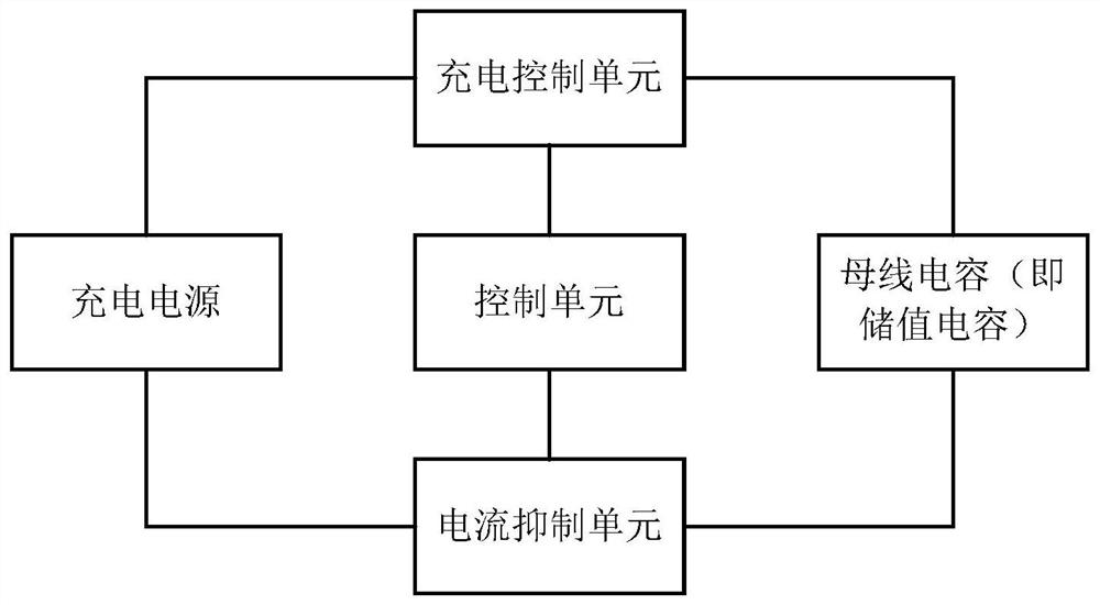
[0035] According to an embodiment of the present invention, a bus charging control device is provided. see figure 1 A schematic structural view of an embodiment of the device of the present invention is shown. The bus charging control device can be applied in the bus charging control of the driver. The bus charging control device of the driver can include: a curr...


PUM


Abstract

The invention discloses a bus charging control device, a driver and a bus charging control method thereof. The device comprises: a control unit used for controlling a branch where a charging control unit is located to be disconnected and controlling a branch where a current inhibition unit is located to be connected under the condition that a driver is connected with a charging power supply; the current inhibition unit used for sampling the input current of the charging power supply and suppressing the change of the input current under the condition that the input current changes according toa sampling result, wherein the control unit is further used for controlling the branch where the current inhibition unit is located to be disconnected and controlling the branch where the charging control unit is located to be connected under the condition that a bus capacitor is charged through the current inhibition unit; and the charging control unit used for controlling the charging power supply to charge the bus capacitor. According to the scheme, the problem that the control difficulty is large when the PTC resistor is used for restraining the input current at the front stage of the driver input circuit can be solved, and the effect of reducing the restraining difficulty of the front-stage input current of the driver input circuit is achieved.

Description

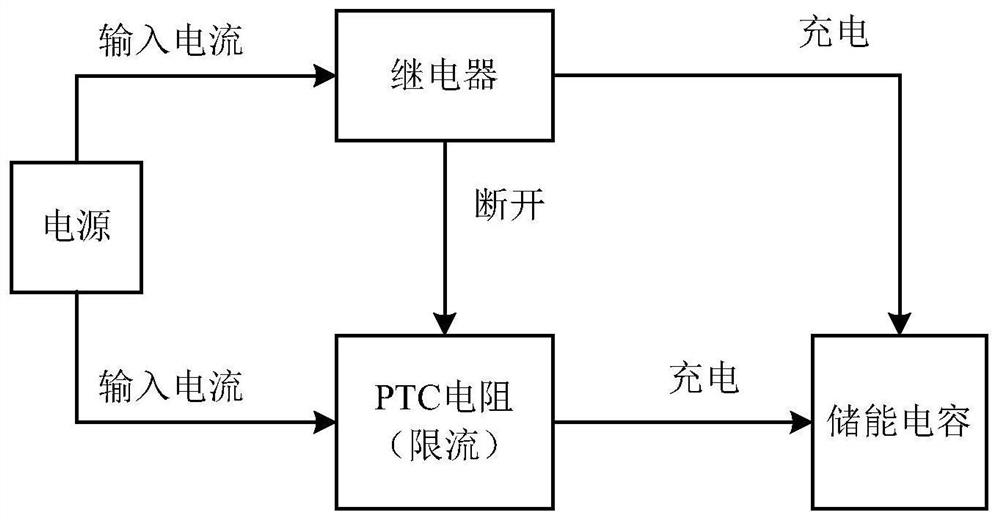
technical field [0001] The invention belongs to the technical field of charging control, and in particular relates to a bus charging control device, a driver and a bus charging control method thereof, in particular to a controllable driver bus charging current change suppression circuit, a driver and a bus charging control method thereof. Background technique [0002] With the development of industrial automation, the demand for drives in the market is also increasing. For low-power drive products, the required bus energy storage capacitors are generally not too large, and the charging time is also short. Too long, but when applied to high-power drive products, especially servo drive products with a common DC bus, larger and more energy storage capacitors are bound to be required. [0003] When the driver works stably, the DC power rectified by the three-phase AC input power supply through the rectifier bridge will supply power to the bus through the relay (that is, charge t...

Claims


Application Information

Patent Timeline
Patent Type & Authority Applications(China)
IPC IPC(8): H02J7/34H02H9/02
CPCH02H9/026H02J7/345
Inventor 王长恺刘亚祥吴元超贾卫东樊柳芝周文杰
Owner GREE ELECTRIC APPLIANCES INC
Learn More