Flat steering engine with inner rotor structure

A technology of inner rotor and steering gear, which is applied in the direction of structural connection, magnetic circuit shape/style/structure, electromechanical device, etc. The effect of optimized design, compact structure, and improved utilization

Pending Publication Date: 2021-01-15
SHENZHEN TATFOOK NETWORK TECH
View PDF0 Cites 2 Cited by
  • Summary
  • Abstract
  • Description
  • Claims
  • Application Information

AI Technical Summary

Problems solved by technology

[0005] Therefore, the technical problem to be solved by the present invention is to overcome the defect that the steering gear in the prior art is too long in the axial direction, which is not conducive to realizing the flat design of the steering gear, so as to provide an inner rotor structure with a compact structure and a small axial size flat servo

Method used


Image

  • Flat steering engine with inner rotor structure
  • Flat steering engine with inner rotor structure
  • Flat steering engine with inner rotor structure

Examples


Embodiment 1

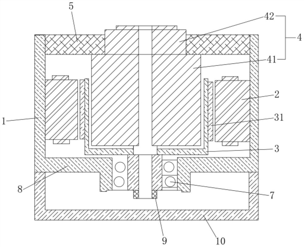
[0041] Such as figure 1 The shown flat steering gear with an inner rotor structure includes: a steering gear housing 1 , a motor stator 2 and a motor rotor 3 located in the steering gear housing 1 , a speed reduction mechanism 4 and a steering gear frame 5 . Wherein, the inside of the steering gear housing 1 has a cavity, and the inner wall of the steering gear housing 1 is also connected with a motor base 8 extending in the cavity, and the cavity in the steering gear housing 1 is divided into a first cavity by the motor base 8. cavity and the second cavity. The motor stator 2 is fixed on the inner wall of the steering gear casing 1 corresponding to the first cavity, and the motor rotor 3 is arranged coaxially with the motor stator 2 inside the motor stator 2 .

[0042] Specifically, the motor rotor 3 is a concave cylindrical structure with an installation chamber inside, and a through hole (not shown in the figure) arranged along the direction of the central axis 6 of the st...

Embodiment 2

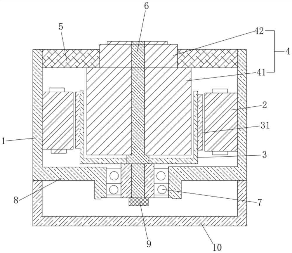
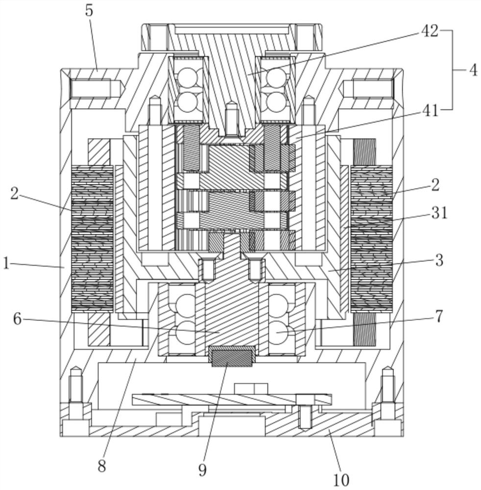
[0055] Such as figure 2 and image 3 As shown, a flat steering gear with an inner rotor structure includes: a steering gear housing 1 , a motor stator 2 and a motor rotor 3 located in the steering gear housing 1 , a speed reduction mechanism 4 and a steering gear frame 5 . Wherein, the inside of the steering gear housing 1 has a cavity, and the inner wall of the steering gear housing 1 is also connected with a motor base 8 extending in the cavity, and the cavity in the steering gear housing 1 is divided into a first cavity by the motor base 8. cavity and the second cavity. The motor stator 2 is fixed on the inner wall of the steering gear casing 1 corresponding to the first cavity, and the motor rotor 3 is arranged coaxially with the motor stator 2 inside the motor stator 2 .

[0056] Specifically, the motor rotor 3 is a concave cylindrical structure with an installation chamber inside, and a through hole (not shown) is provided in the middle of the bottom wall along the di...


PUM


Abstract

The invention discloses a flat steering engine of an inner rotor structure. The flat steering engine comprises a steering engine shell, a motor stator fixed in the steering engine shell, a motor rotorcoaxially arranged in the motor stator in a sleeving mode, and a speed reducing mechanism, wherein the motor rotor is of a cylinder structure with an installation cavity inside, and a through hole isformed in the middle of the motor rotor in the direction of the central axis of the steering engine shell; the speed reducing mechanism is kept fixed relative to the steering engine shell through thesteering engine base, and is partially suspended in the mounting cavity of the motor rotor, and a central hole coaxial with the through hole is formed in the middle of the speed reducing mechanism; ashaft body matched with the through hole and the central hole is rotationally connected to the steering engine shell through a bearing; power of the motor rotor is transmitted to the input end of thespeed reducing mechanism through the shaft body. The flat steering engine is advantaged in that a part of the speed reducing mechanism is suspended in the mounting cavity of the motor rotor, so the axial length of the steering engine is shortened, the structure of the steering engine is more compact, and the steering engine further has the advantages of large output end torque, high transmissionefficiency, stable transmission, long service life and high integrity.

Description

technical field [0001] The invention relates to a flat steering gear, in particular to a flat steering gear with an inner rotor structure built in a reduction mechanism. Background technique [0002] The steering gear is a key component of automation equipment such as robots, and the performance of the steering gear directly affects the overall performance of the robot. Most of the current robots are relatively heavy and the overall size is relatively large, so it is difficult to apply to some high-performance robots (such as legged robots, exoskeleton robots, bionic robots, etc.) that are small in size but have high requirements for output torque and torque fluctuations. In the application occasion. The self-weight and axial size of the steering gear are the key factors affecting the overall size of the robot. How to reduce the self-weight and axial length of the steering gear as much as possible under the condition of equal power, so as to realize the flat and lightweight...

Claims


Application Information

Patent Timeline
Patent Type & Authority Applications(China)
IPC IPC(8): H02K7/116F16H57/02H02K5/173H02K5/04H02K1/27H02K11/21H02K11/30
CPCF16H57/02F16H2057/02034F16H2057/02086H02K1/278H02K5/04H02K5/1735H02K7/116H02K2201/03H02K11/21H02K11/30
Inventor 李铁才张明俊陈时刘柯孙虎
Owner SHENZHEN TATFOOK NETWORK TECH
Why Eureka
Try Eureka