Combined gasification furnace burner

A gasifier and combined technology, which is applied in the field of combined gasifier burners, can solve the problem of the gasifier heating up, the pressure increasing speed is slow, the inability to accurately judge the gasifier temperature, and the small amount of coal input in the gasifier, etc. problems, to achieve the effect of increasing the amount of coal input, reducing the impact, and reducing the economic loss of the enterprise

Pending Publication Date: 2021-01-19
陕西宏远燃烧设备有限公司
View PDF0 Cites 1 Cited by
  • Summary
  • Abstract
  • Description
  • Claims
  • Application Information

AI Technical Summary

Problems solved by technology

[0004] The problems that exist in this way are: 1. Reversing the burner needs to be manually operated at the production site. Generally speaking, the reversing time is half an hour to 1 hour, which takes a long time. Moreover, a single burner is used for production, making the gasifier 2. In the process of feeding pulverized coal and oxygen into the pulverized coal burner after the gasifier is reversed, the pulverized coal and oxygen can only be sent to the middle position of the gasifier inlet, and the combustion is also difficult. It can only be burned in the middle position, so that the temperature in the upper middle position of the gasifier furnace is the highest, and the temperature near the inner wall is lower. A certain temperature deviation, especially when the process fluctuates, cannot accurately judge the real temperature in the gasifier, which affects the process operation and even seriously affects the output; 3. The temperature difference between the middle and the inner wall of the gasifier causes The gasifier is heating up and the pressure is rising slowly

Method used


Image

  • Combined gasification furnace burner
  • Combined gasification furnace burner
  • Combined gasification furnace burner

Examples


Embodiment Construction

[0033] The following is attached Figure 1-Figure 7 For a further detailed introduction to the present invention, it should be noted that the orientation words such as up, down, left, and right involved in this application are consistent with the up, down, left, and right orientations of each figure in the accompanying drawings, and all the orientation words are only for clearly expressing the structure of the application , but not limited to restrictions on the specific location of the actual product.

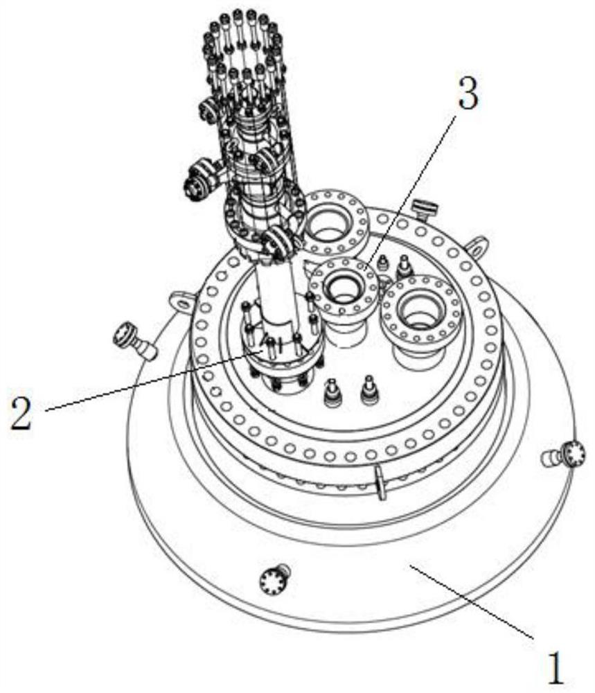
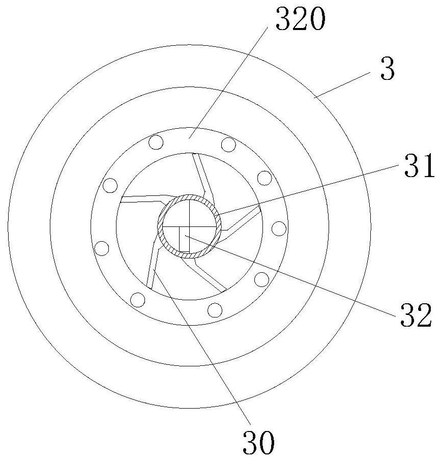
[0034] A combined gasifier burner, such as figure 1 As shown, including the burner base 1, the burner base 1 is provided with an ignition start-up burner 3, and the outside of the ignition start-up burner 3 is provided with at least three pulverized coal burners 2, and each pulverized coal burner 2 is evenly distributed on the same On the virtual circle, the center of the virtual circle is located on the geometric center of the ignition burner 3 . The burner base 1 is connec...


PUM

PropertyMeasurementUnit
diameteraaaaaaaaaa
diameteraaaaaaaaaa

Abstract

The invention discloses a combined type gasification furnace burner which comprises a burner base; the burner base is vertically installed at the top of a gasification furnace, an ignition starting burner is arranged on the burner base, at least two pulverized coal burners are arranged on the outer side of the ignition starting burner, and the pulverized coal burners are evenly distributed on thesame virtual circle, so that the complex operation procedure of switching ignition start-up burners during start-up of the gasification furnace is omitted. On one hand, the coal feeding amount of thegasification furnace can be increased, the defects that the coal feeding amount of the gasification furnace is small and the productivity is low when a single burner is arranged are overcome, on the other hand, pulverized coal and oxygen can be sprayed into the gasification furnace more evenly through multi-nozzle arrangement, temperature deviation in a hearth of the gasification furnace can be eliminated, and an accurate basis is provided for judging the temperature in the gasification furnace. The influence on the process operation is reduced, the influence on the productivity of the gasification device caused by frequent startup and shutdown is reduced, the economic loss of enterprises is reduced, the economic benefit is improved, and meanwhile, the heating and boosting speed and the accuracy of remote operation during normal operation of the gasification furnace are improved.

Description

technical field [0001] The invention relates to the technical field of gasifier burners, in particular to a combined gasifier burner. Background technique [0002] The gasifier in a chemical plant is the primary equipment for preparing the coal gas mixture required by the chemical process. The working principle of the gasifier is that coal powder or coal slurry and oxygen (dry coal powder needs to be added with steam) are burned in the gasifier for oxidation and reduction gasification reactions. The carbon in the coal is oxidized and reduced into raw material gas after incomplete combustion. . At high temperature, the ash in the coal turns into liquid slag and is discharged from the gasifier. [0003] The gasifier is inseparable from the burner when it is started or in normal operation. According to the function and use, the burner includes the ignition start-up burner and the pulverized coal burner; among them, the ignition start-up burner is used for gasification during ...

Claims


Application Information

Patent Timeline
Patent Type & Authority Applications(China)
IPC IPC(8): C10J3/50
CPCC10J3/50
Inventor 刘自涛崔旋旋孙博雷浩张海龙
Owner 陕西宏远燃烧设备有限公司
Why Eureka
Try Eureka