Device and method for preparing thermal fuel gas for glass kiln by anthracite pressurized moving bed

A technology of glass kiln and fuel gas, applied in the field of coal-to-gas, which can solve the problems of high pollution, low energy utilization rate, and small gas generation, and achieve the effects of high energy utilization rate, reduced difficulty in wastewater treatment, and reduced design scale

Inactive Publication Date: 2017-09-26
SHANXI JINMEI GRP TECH RESEACH INST
View PDF4 Cites 0 Cited by
  • Summary
  • Abstract
  • Description
  • Claims
  • Application Information

AI Technical Summary

Problems solved by technology

[0004] The present invention solves the technical problems such as small gas production, heavy pollution and low energy utilization rate of the existing normal-pressure fixed-bed g

Method used


Image

  • Device and method for preparing thermal fuel gas for glass kiln by anthracite pressurized moving bed

Examples


Embodiment 1

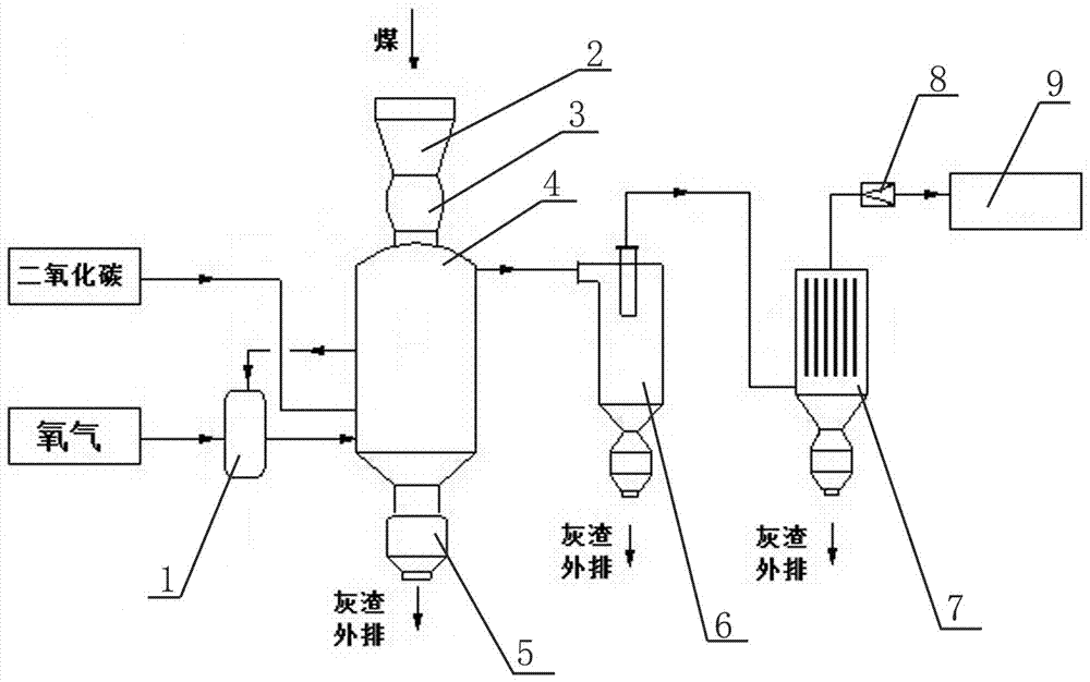
[0034] A method for preparing hot fuel gas for a glass kiln with an anthracite pressurized moving bed, comprising the following steps:

[0035] a. Add anthracite from the raw coal bunker to the gasifier;

[0036] b. Pure oxygen and recovered CO from oxygen-making equipment in the future 2 The gas is mixed in the mixer to form a gasification agent, and the gasification agent is transported to the gasification furnace body by the mixer;

[0037] c. The gasification furnace body is divided into drying layer, dry distillation layer, reduction layer, oxidation layer and ash layer from top to bottom. The gasification agent passing into the gasification furnace body first exchanges heat with the ash layer, and then enters the oxide layer with oxygen and A violent combustion reaction occurs when the hot coal seam contacts, and CO is generated 2 ; The gas after the oxidation reaction enters the reducing layer upwards, and in the reducing layer CO 2 It reacts with coal to generate CO...

Embodiment 2

[0044] The particle size is 6~50 mm, the as received basis ash content is 13~15%, the as received basis fixed carbon content is 70~75%, the as received basis volatile matter content is 6~8%, the as received basis total sulfur content is less than 0.5%, Softening temperature (T 2 ) greater than 1500 ℃, crushing strength greater than 96%, and thermal stability greater than 95% are added to the gasifier through coal bunkers and coal locks.

[0045] Gasification agent oxygen 2165 Nm 3 / h (99.6%, 0.6 MPa) and CO 2 2165 Nm 3 / h (0.6 MPa), after mixing, enter the gasifier for redox reaction. Into the coil CO 2 The temperature is 10°C, and the outlet coil temperature is about 350°C.

[0046] The heat production fuel gas volume of a single furnace is 10324 Nm 3 / h, pressure 0.5 MPa, temperature about 500 ℃, after dust removal by cyclone dust collector and dry dust collector (dust content is less than 10 mg / Nm³, pressure 0.45 MPa, temperature 450 ℃), after the pressure is adjuste...


PUM

PropertyMeasurementUnit
Particle sizeaaaaaaaaaa
Softening temperatureaaaaaaaaaa

Abstract

The invention relates to the field of coal gas, in particular to a device and a method for preparing thermal fuel gas for a glass kiln by an anthracite pressurized moving bed. The adopted technical scheme comprises the following steps: adding anthracite with a particle size of 6-50 mm into a feed lock hopper from a raw coal bunker, entering a gasification furnace, entering from the bottom of the gasification furnace after oxygen from oxygen making equipment is mixed with recovered CO2, performing heat exchange with an ash layer at the lower part, generating intense oxidation reduction reaction with a coal bed in the middle, performing heat exchange with the coal bed at the upper part, then generating the thermal fuel gas, flowing out the fuel gas from the upper part of the gasification furnace, entering a cyclone separator to remove large particles of coal ash impurities, entering a dry type dust remover, regulating the pressure to a required range after the fuel gas is subjected to dust removal and conveying into a glass kiln for use. The thermal fuel gas prepared by the device and the method provided by the invention can directly enter the glass kiln without the steps of washing, temperature reduction, dust removal, desulfurization, purification and sewage treatment; the operating process is simple, the energy utilization is reasonable, and cleanness and environmental protection are realized.

Description

technical field [0001] The invention relates to the field of coal gas production, in particular to a device and method for preparing hot fuel gas for glass kiln with an anthracite pressurized moving bed. Background technique [0002] There are two main sources of fuel gas currently used in the glass furnace industry: natural gas and artificial gas. The price of natural gas is high, gas supply is unstable, and artificial gas is produced by atmospheric fixed bed, which has problems such as low production capacity, excessive dispersion, low heat utilization rate, and serious pollution. With the increasingly stringent national environmental protection policies, in order to solve the problems of low production capacity, scattered layout, environmental pollution, and increasingly serious smog existing in existing gasification technologies, an efficient and low-pollution gas supply solution is urgently needed to meet market transformation needs , to produce efficient and clean ene...

Claims


Application Information

Patent Timeline
IPC IPC(8): C10J3/00C10J3/84C10J3/60
CPCC10J3/00C10J3/60C10J3/84C10J2300/093C10J2300/1603
Inventor 李金洲楚可嘉
Owner SHANXI JINMEI GRP TECH RESEACH INST
Why Eureka
Try Eureka