Automatic dough filling machine
An automatic filling machine and dough technology, applied in dough extruders, dough cutting machines, dough processing, etc., can solve the problems of time delay, inconsistent dough weight, sticking to hands or knives, etc., to improve work efficiency , the effect of convenient work
- Summary
- Abstract
- Description
- Claims
- Application Information
AI Technical Summary
Problems solved by technology
Method used
Image
Examples
Embodiment 1
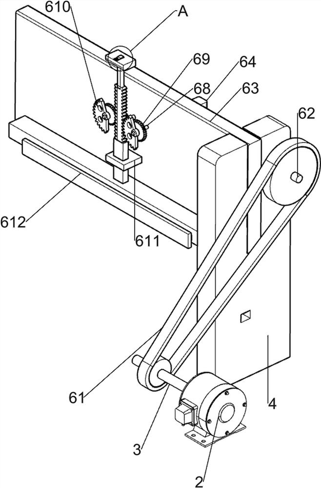
[0067] A dough automatic filling machine such as figure 1 As shown, it includes a bottom plate 1, a motor 2, a first transmission rod 3, a bracket 4, a transmission mechanism 5, a material cutting mechanism 6, a material retaining mechanism 7 and a material extrusion mechanism 8, and a motor 2 is provided on the front right side of the top of the bottom plate 1. , the output shaft of the motor 2 is provided with a first transmission rod 3, the other end of the first transmission rod 3 is rotationally connected with the front part of the right side of the base plate 1, a support 4 is arranged symmetrically on the rear side of the top of the base plate 1, and a transmission rod is provided on the top of the base plate 1. Mechanism 5, material cutting mechanism 6 is arranged between the upper parts of the opposite side of support 4, material extruding mechanism 8 is arranged between the upper parts of the front side of support 4, and material blocking mechanism 7 is arranged on the ...
Embodiment 2
[0070] On the basis of Example 1, such as figure 2 , image 3 , Figure 4 and Figure 5 As shown, the transmission mechanism 5 includes a first missing gear 51, a second transmission rod 52, a first gear 53, a fourth rotating rod 54, a roller 55, a first support plate 56, a first fixed rod 57 and a conveyor belt 58. The right part of a transmission rod 3 is provided with a first missing gear 51, and the left and right sides of the upper part of the front side of the bottom plate 1 are rotatably provided with a second transmission rod 52, and the right part of the second transmission rod 52 is provided with a first gear 53. A gear 53 meshes with the first missing gear 51, and a fourth rotating rod 54 is rotated between the left and right sides of the upper rear side of the bottom plate 1, and a roller 55 is provided on the second transmission rod 52 and the fourth rotating rod 54. , a conveyor belt 58 is arranged between the rollers 55, a first fixed rod 57 is arranged on t...
Embodiment 3
[0075] On the basis of Example 2, such as figure 1 , Figure 6 , Figure 7 , Figure 8 and Figure 9 As shown, the extruding mechanism 8 includes a charging box 81 and an extruding rod 82 , the charging box 81 is arranged between the upper front side of the bracket 4 , and an extruding rod 82 is arranged on a certain part of the blocking mechanism 7 .
[0076] When people need to use this device to divide the dough, the dough is put into the charging box 81, then the material board for the dough is put on the conveyor belt 58, and then the motor 2 is started, and the output shaft of the motor 2 drives the first transmission rod 3 Rotate, so that the conveyor belt 58 drives the material plate to move forward intermittently. When the rack bar 613 moves downward, it drives the material retaining mechanism 7 to move downward. The material retaining mechanism 7 no longer blocks the dough, and the material retaining mechanism 7 drives the extruding rod 82 moves downward to extru...
PUM
 Abstract
Description
Claims
Application Information
 - R&D
- Intellectual Property
- Life Sciences
- Materials
- Tech Scout
- Unparalleled Data Quality
- Higher Quality Content
- 60% Fewer Hallucinations
Browse by: Latest US Patents, China's latest patents, Technical Efficacy Thesaurus, Application Domain, Technology Topic, Popular Technical Reports.
© 2025 PatSnap. All rights reserved.Legal|Privacy policy|Modern Slavery Act Transparency Statement|Sitemap|About US| Contact US: help@patsnap.com


