Extrusion type expansion anchor

An expansion anchor and extrusion technology, which is applied in the field of bone implantation anchors, can solve the problems of difficult knocking of the anchor, long screwing time, reduction of the overall time and difficulty of the operation, etc. Effect

Pending Publication Date: 2021-01-22
HANGZHOU REJOIN MASTIN MEDICAL INSTR CO LTD
View PDF10 Cites 3 Cited by
  • Summary
  • Abstract
  • Description
  • Claims
  • Application Information

AI Technical Summary

Problems solved by technology

[0003] The existing knock-in and screw-in anchors simply rely on the extrusion and anchoring between the teeth on the outside of the anchor body and the inner wall of the bone hole to provide pull-out resistance. Since the outer diameter of the anchor is fixed, in order to improve pull-out The force inevitably requires a sufficient number of teeth, which makes it difficult to knock in the anchor or takes a long time to screw in, which affects the overall operation time
[0004] Patent CN201520214267.0 discloses an anchor, which uses the expansion of the head diameter of the anchor body to increase the extrusion force between the anchor body and the bone hole, thereby enhancing the pull-out resistance of the anchor, and internal expansion The number of thread teeth of the element is less, which reduces th

Method used


Image

  • Extrusion type expansion anchor
  • Extrusion type expansion anchor
  • Extrusion type expansion anchor

Examples


Embodiment Construction

[0034] The present invention will be further described below in conjunction with specific embodiments. It should be understood that these examples are only used to illustrate the present invention and not to limit the scope of the present invention. In addition, it should be understood that after reading the content taught by the present invention, those skilled in the art can make various changes or modifications to the present invention, and these equivalent forms also fall within the scope defined by the appended claims of the present application.

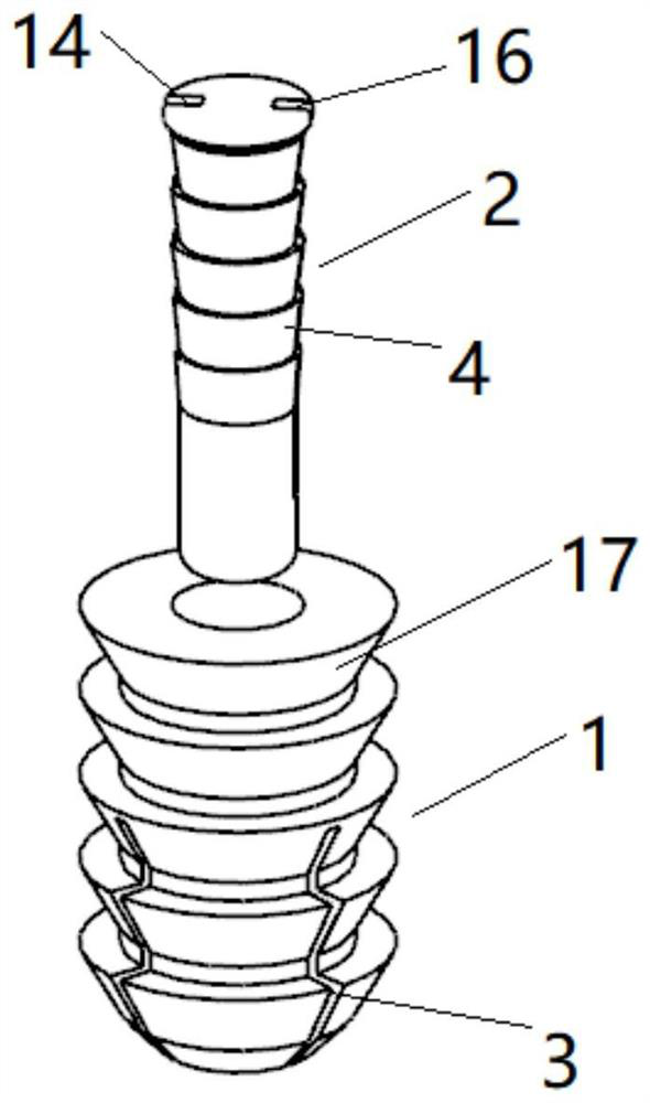
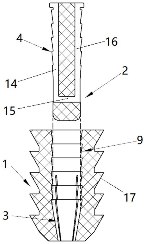
[0035] An extruded expansion anchor such as Figures 1 to 4 As shown, it includes an anchor body 1 and an expansion element 2, a gap 3 is provided near the front end 10 of the anchor body, and the expansion element 2 is used to insert the inner cavity of the anchor body 1 from the rear end 11 of the anchor body to make the front end of the anchor body 10 diameter. to expand;

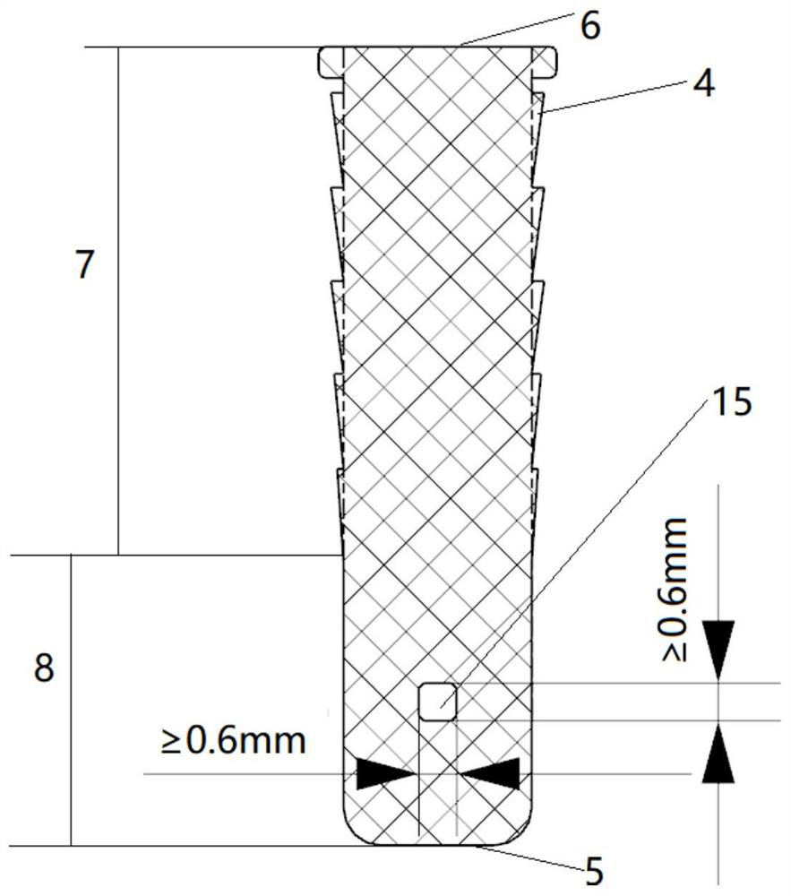
[0036] The expansion element 2 is a cylindrical st...


PUM


Abstract

The invention relates to an extrusion type expansion anchor. The extrusion type expansion anchor comprises an anchor body and an expansion element, wherein a notch is formed in a position near the front end of the anchor body, the expansion element is used for being inserted into an inner cavity of the anchor body from the rear end of the anchor body to enable the front end of the anchor body to expand in the radial direction, and an annular groove A is formed in the inner side wall of the anchor body; the expansion element is of a columnar structure, and an annular protrusion B is arranged onthe side wall of the expansion element; and the annular groove A and the annular protrusion B are matched with each other to achieve retaining clamping fit. According to the extrusion type expansionanchor, the anti-pulling force of the anchor body is increased by adopting a self-locking expansion structure, so that the anchor body is not prone to falling off after being implanted into a bone, the number of elements used for anchoring outside the anchor body does not need to be increased, and the circumstance that the overall operation time is influenced due to the fact that the anchor is difficult to knock in or the screwing-in time is long is avoided; and meanwhile, a one-way self-locking structure of the anchor body and the expansion element is formed by utilizing the retaining clamping fit of the annular groove A and the annular protrusion B, so that the expansion element is not prone to loosening after being extruded into the anchor body, the expansion element does not need to have high shear strength, and the expansion element can be suitable for an absorbable material and a PEEK material.

Description

technical field [0001] The invention belongs to the technical field of bone implantation anchors, and relates to an extruded expansion anchor. Background technique [0002] Anchors are mainly used clinically for tendon soft tissue injuries such as shoulder joints and knee joints. By implanting the anchors in the bone hole, the torn tendon tissue is fixed on the bone with sutures, so as to achieve tendon-bone healing. Purpose, since the human joint is active for a long time, the stability of its implantation in the bone is particularly important. [0003] Most of the existing knock-in and screw-in anchors simply rely on the extrusion and anchoring between the teeth on the outside of the anchor body and the inner wall of the bone hole to provide anti-pullout force. The force must require a sufficient number of teeth, which makes it difficult to drive the anchor in or takes a long time to screw in, which affects the overall operation time. [0004] Patent CN201520214267.0 dis...

Claims


Application Information

Patent Timeline
IPC IPC(8): A61B17/04A61L31/06A61L31/14
CPCA61B17/0401A61L31/148A61L31/06A61B2017/0424A61B2017/0408A61B2017/00004
Inventor 甄妮李凌晨蒋冠森徐胜军
Owner HANGZHOU REJOIN MASTIN MEDICAL INSTR CO LTD
Why Eureka
Try Eureka