Exhaust pipe deep bolt hole machining equipment

A technology for processing equipment and exhaust pipes, used in metal processing equipment, drilling/drilling equipment, metal processing machinery parts, etc., can solve problems such as restricting product development and application, economic loss, and difficulty in operation

Inactive Publication Date: 2021-01-22
吴功城
View PDF1 Cites 2 Cited by
  • Summary
  • Abstract
  • Description
  • Claims
  • Application Information

AI Technical Summary

Problems solved by technology

The product is relatively large, and the bolt holes on the air intake flange surface are deep. When drilling, it is necessary to drill from both ends separately. Not only is the operation difficult, but also the coaxiality of the drilling is difficult to ensure. and processing equipment, etc., the processing position of the drilling at both ends is prone to out-of-tolerance, which cannot meet the customer's technical specifications and use requirements, and even lead to the scrapping of the product, which brings serious economic losses to the enterprise and thus hinders production. The improvement of efficiency has always restricted the development and application of products
[0005] The device cannot adaptively clamp water-jacketed exhaust manifolds of different sizes

Method used


Image

  • Exhaust pipe deep bolt hole machining equipment
  • Exhaust pipe deep bolt hole machining equipment
  • Exhaust pipe deep bolt hole machining equipment

Examples


Embodiment Construction

[0039] The following description serves to disclose the present invention to enable those skilled in the art to carry out the present invention. The preferred embodiments described below are only examples, and those skilled in the art can devise other obvious variations.

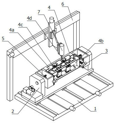
[0040] refer to figure 1 As shown, an exhaust pipe deep bolt hole processing equipment includes:

[0041] Heavy-duty horizontal translation table 1;

[0042] The output end of the rotating assembly 2 is relatively coaxially arranged on both sides of the top of the working part of the heavy-duty horizontal translation table 1;

[0043] The spacing adjustment assembly 3, the working direction of which is vertically arranged on the output end of the rotation assembly 2;

[0044] Clamping assembly 4, said clamping assembly 4 includes a fixed splint 4a, a movable splint 4b, an adjustable abutment 4c and a corner pressing cylinder 4d, said splints are side by side and horizontal, and their two ends are respecti...


PUM


Abstract

The invention relates to the technical field of machining equipment, in particular to exhaust pipe deep bolt hole machining equipment which comprises a heavy horizontal moving table, rotating assemblies, a distance adjusting assembly, clamping assemblies, end abutting assemblies, a gantry lifting translation assembly and a long shaft drilling assembly; the rotating assemblies are arranged at the two sides of the top end of a working part of the heavy horizontal moving table; the distance adjusting assembly is vertically arranged at the output ends of the rotating assemblies; the clamping assemblies comprise fixed clamping plates, movable clamping plates, adjustable abutting devices and corner pressing air cylinders, wherein the clamping plates are horizontally arranged side by side, the two ends of the clamping plates are fixedly connected with a fixed portion and a movable portion of the distance adjusting assembly correspondingly, the adjustable abutting devices and the corner pressing air cylinders are arranged at the opposite sides of the clamping plates at equal intervals, and the working ends of the adjustable abutting devices are opposite to the working ends of the corner pressing air cylinders in the radial directions of the clamping plates; the end abutting assemblies are arranged between the clamping plates; the gantry lifting translation assembly is arranged at the top of one end of the heavy horizontal moving table; and the long shaft drilling assembly is arranged at one side of a lifting part of the gantry lifting translation assembly. The equipment can adaptively clamp and position exhaust pipes of different sizes.

Description

technical field [0001] The invention relates to the technical field of mechanical processing equipment, in particular to an exhaust pipe deep bolt hole processing equipment. Background technique [0002] The water jacket exhaust manifold is widely used in high-power marine engines or other special power equipment. The exhaust manifold of the engine is cooled by the water jacket to prolong the service life of the exhaust manifold. [0003] In the field of mechanical processing technology, the shape of some parts processing parts is complex, which brings great difficulties and inconveniences to processing and testing. For example, the water jacket exhaust manifold, due to the complex structure and particularity of the product, several bolt holes for installation and fixing need to be processed on the inlet flange surface. The product is relatively large, and the bolt holes on the air intake flange surface are deep. When drilling, it is necessary to drill from both ends separa...

Claims


Application Information

Patent Timeline
Patent Type & Authority Applications(China)
IPC IPC(8): B23B41/00B23B47/00B23B47/18B23Q3/08
CPCB23B41/00B23B47/00B23Q3/08B23Q5/22
Inventor 吴功城
Owner 吴功城
Why Eureka
Try Eureka