
Multi-wire cutting machine

A multi-wire cutting machine and frame technology, which is applied to metal sawing equipment, sawing machine devices, sawing machine accessories, etc., can solve the problems of slow wiring speed, more labor, and large resistance, so as to save wiring time and reduce wiring time, the effect of avoiding major losses

Pending Publication Date: 2021-01-22
苏州庆耀精密机械科技有限公司
View PDF0 Cites 0 Cited by
  • Summary
  • Abstract
  • Description
  • Claims
  • Application Information

AI Technical Summary

Problems solved by technology

[0002] When wiring the existing multi-wire cutting machine, it is necessary to wind a very long metal wire on dozens of rollers. Due to the large number of rollers that need to be wound, the resistance is large, and the entire roller system cannot be dragged by pulling the metal wire. At present, the control system is used to control the synchronous and slow rotation of the take-up and pay-off reel and the main reel, and the wire is slowly wound up with the rotation of the reel. This method requires two people to carry out wiring for more than two hours, and the wiring speed is slow. It requires a lot of labor, which affects the overall efficiency of the multi-wire cutting machine. At the same time, when the existing multi-wire cutting machine breaks the metal wire during high-speed operation, it cannot be found in time, and the equipment will be damaged.

Method used


Image

  • Multi-wire cutting machine
  • Multi-wire cutting machine
  • Multi-wire cutting machine

Examples


Embodiment Construction

[0017] The present invention will be further described below in conjunction with the accompanying drawings and specific embodiments.

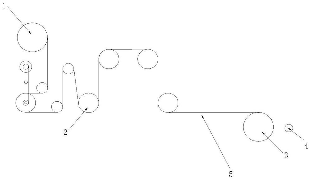
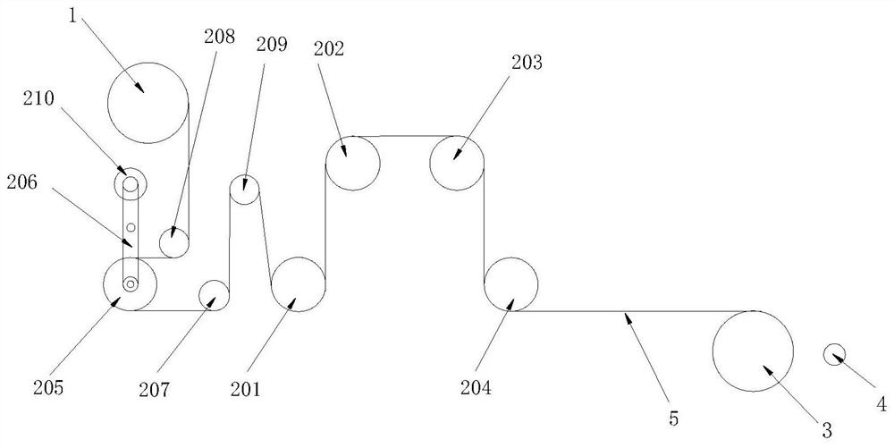
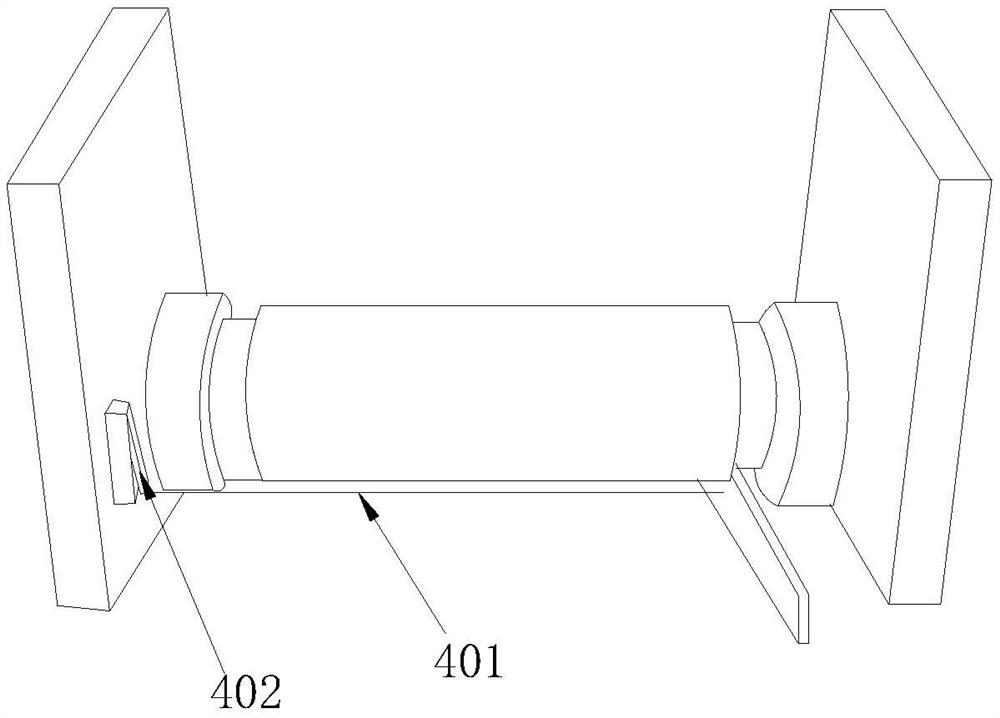
[0018] Such as figure 1 The shown multi-wire cutting machine includes a frame, and the frame is sequentially provided with a wire releasing mechanism 1 for putting metal wires 5, a wiring mechanism 2 for wiring, and a wiring mechanism 2 for realizing cutting. The rewinding mechanism 3 for rewinding the metal wire 5 and the wire break detection mechanism 4 for detecting whether the metal wire 5 is broken also include a control mechanism for controlling the multi-wire cutting machine. Mechanism 2, winding mechanism 3 and disconnection detection mechanism 4 are electrically connected with the control mechanism respectively, and described pay-off mechanism 1 is used for putting metal wire 5, and described wiring mechanism 2 is used for wiring before wire cutting, and described winding mechanism 3 is used to wind up the metal wire 5 after cutting. ...


PUM


Abstract

The invention relates to the field of cutting, and discloses a multi-wire cutting machine which comprises a rack. The rack is sequentially provided with a pay-off mechanism used for paying off metal wires, a wire distribution mechanism used for wire distribution, a winding mechanism used for winding cut metal wires and a wire breakage detection mechanism used for detecting whether metal wires arebroken or not from left to right. The multi-wire cutting machine further comprises a control mechanism used for controlling the multi-wire cutting machine. A driving motor in the wire distribution mechanism in the multi-wire cutting machine is in a torque control mode so that wire distribution work can be conducted only by overcoming part of friction torque of a driving main shaft, wire distribution time is shortened, and the wire distribution speed of the multi-wire cutting machine is increased; and the pay-off mechanism pays off wires according to the angular speed and the angular acceleration, detected by an encoder, of swing of a swing rod, so that the resistance of a roller system in the wire distribution process is greatly reduced, the wire breakage detection mechanism is used for detecting whether metal wires are broken or not, when it is detected that metal wires are broken, operation can be stopped in time, an alarm is given, and heavy losses are avoided.

Description

technical field [0001] The invention relates to the field of cutting, in particular to a multi-wire cutting machine. Background technique [0002] When wiring the existing multi-wire cutting machine, it is necessary to wind a very long metal wire on dozens of rollers. Due to the large number of rollers that need to be wound, the resistance is large, and the entire roller system cannot be dragged by pulling the metal wire. At present, the control system is used to control the synchronous and slow rotation of the take-up and pay-off reel and the main reel, and the wire is slowly wound up with the rotation of the reel. This method requires two people to carry out wiring for more than two hours, and the wiring speed is slow. It requires a lot of labor, which affects the overall efficiency of the multi-wire cutting machine. At the same time, when the existing multi-wire cutting machine breaks the metal wire during high-speed operation, it cannot be found in time, and the equipmen...

Claims


Application Information

Patent Timeline
Patent Type & Authority Applications(China)
IPC IPC(8): B23D57/00B23D59/00
CPCB23D57/0007B23D57/0061B23D57/0069B23D59/001
Inventor 王卫锋
Owner 苏州庆耀精密机械科技有限公司
Learn More