
Continuous vacuum magnetron sputtering coating device and coating production line

A vacuum magnetron sputtering and coating device technology, applied in sputtering coating, vacuum evaporation coating, ion implantation coating and other directions, can solve the problems of reducing coating accuracy, ignition, accumulation of cations, etc., to expand the application range effect

Active Publication Date: 2021-01-22
凯盛信息显示材料(洛阳)有限公司
View PDF8 Cites 3 Cited by
  • Summary
  • Abstract
  • Description
  • Claims
  • Application Information

AI Technical Summary

Problems solved by technology

[0004] However, there are still many defects in the existing technology, such as: the sputtering target receives positive charges for a long time, so that the accumulation of cations on the sputtering target is too much, which is easy to cause the phenomenon of sparking between electrodes, resulting in defects in the film and reducing the coating accuracy

Method used


Image

  • Continuous vacuum magnetron sputtering coating device and coating production line
  • Continuous vacuum magnetron sputtering coating device and coating production line
  • Continuous vacuum magnetron sputtering coating device and coating production line

Examples


Embodiment Construction

[0036] The following will clearly and completely describe the technical solutions in the embodiments of the present invention with reference to the accompanying drawings in the embodiments of the present invention. Obviously, the described embodiments are only some, not all, embodiments of the present invention. Based on the embodiments of the present invention, all other embodiments obtained by persons of ordinary skill in the art without making creative efforts belong to the protection scope of the present invention.

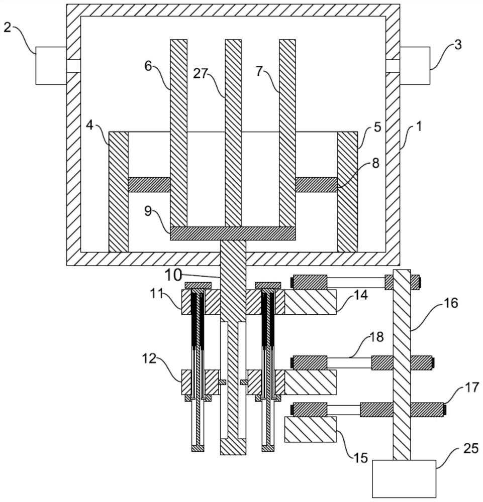
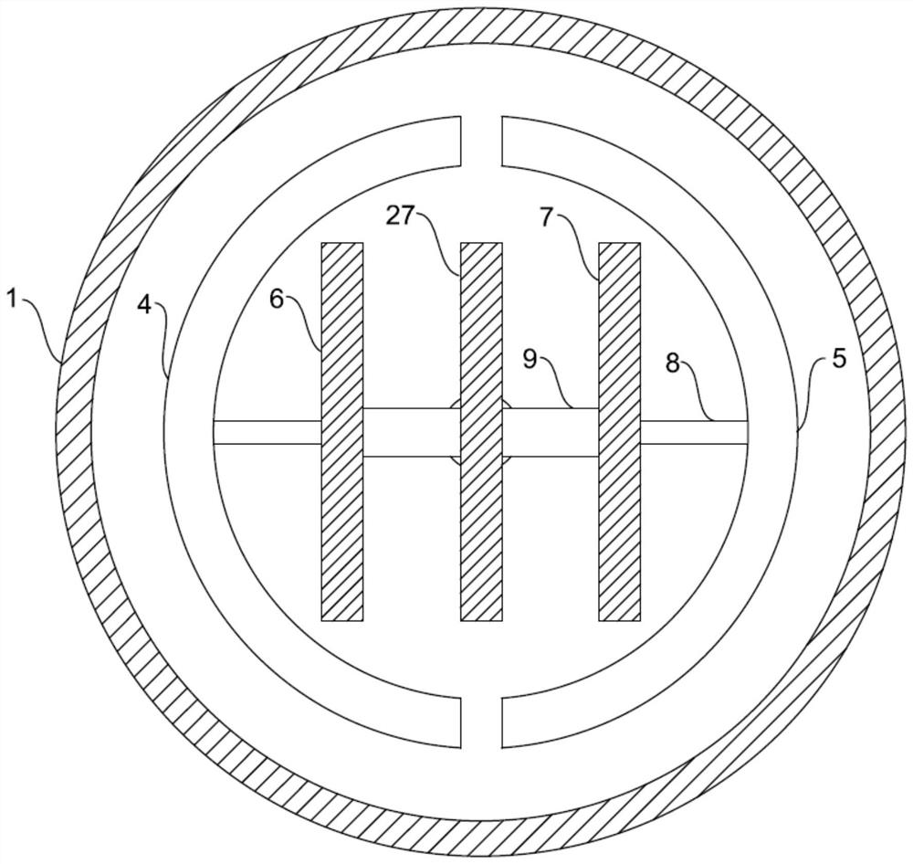
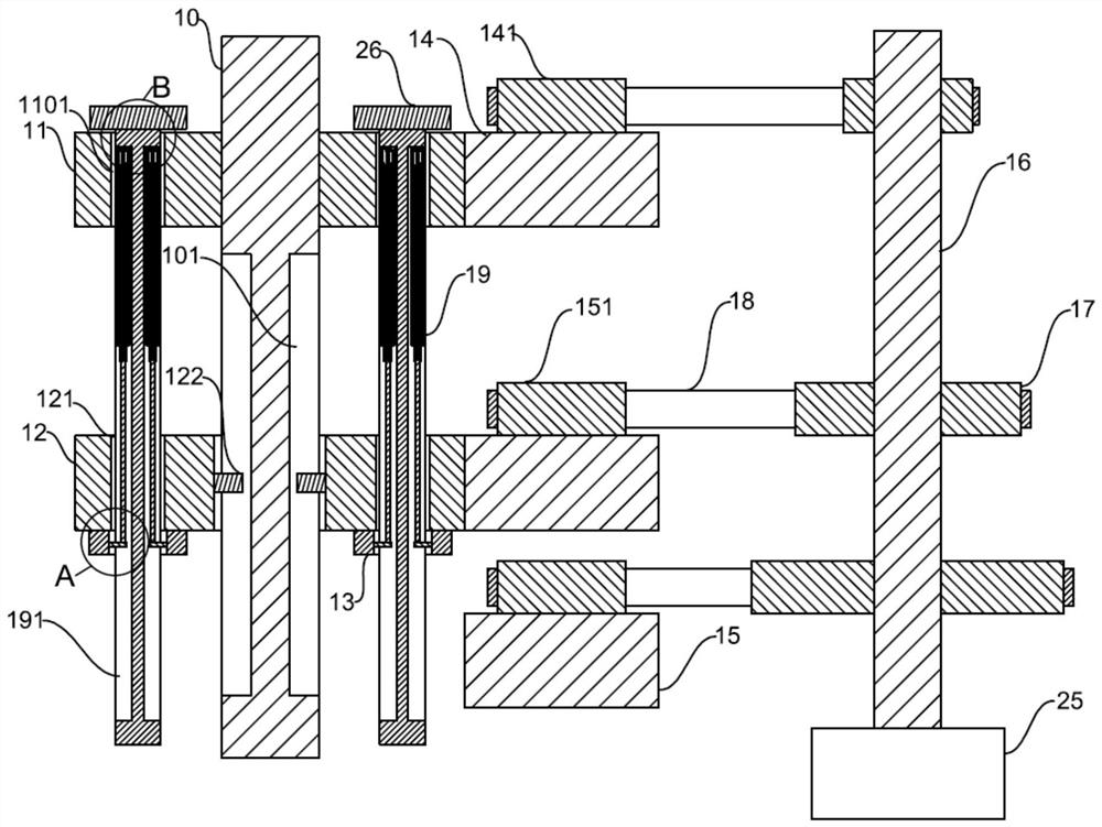
[0037] see Figure 1-8 , the present invention provides a technical solution:

[0038] A continuous vacuum magnetron sputtering coating device, including a vacuum chamber 1, a vacuum unit, an air distribution unit, an alternate coating unit and a variable speed rotation unit, the vacuum unit includes a vacuum pump 2, the suction port of the vacuum pump 2 communicates with the vacuum chamber 1, and the vacuum pump 2 Provide vacuum environment for sputter coati...


PUM


Abstract

The invention discloses a continuous vacuum magnetron sputtering coating device and a coating production line. The continuous vacuum magnetron sputtering coating device comprises an alternate coatingunit and a variable-speed rotating unit, a first sputtering target and a second sputtering target which are opposite to each other are movably arranged between a positive electrode power connection annular plate and a negative electrode power connection annular plate, and gear teeth of a first driven rotating gear and gear teeth of a second driven rotating gear are complementary; and a plurality of variable-speed rotating wheels with different sizes are fixedly connected to a driving rotating rod, empty grooves are formed in the two sides of an adjusting rod, and adjusting mechanisms are fixedly arranged in the empty grooves. When the continuous vacuum magnetron sputtering coating device is used, the positive electrode power connection annular plate and the negative electrode power connection annular plate are arranged, so that the two sides of a part to be coated are alternately coated, and positive ions accumulated on a target surface are neutralized; and through the arrangement of the multiple variable-speed rotating wheels with the different sizes, multiple second driving rotating gears and the adjusting mechanisms, the coating thicknesses of the two sides of the part to be coated are different, different process requirements are met, and the application range of the device is widened.

Description

technical field [0001] The invention relates to the technical field of sputtering coating equipment, in particular to a continuous vacuum magnetron sputtering coating device and a coating production line. Background technique [0002] At present, magnetron sputtering coating technology is a widely used vacuum coating technology method, which is widely used in optics, microelectronics decoration and other industrial fields to provide reliable and stable thin film coatings. However, the existing magnetron sputtering devices still have many defects, such as lack of multi-face coating capability. [0003] In the prior art, a magnetron sputtering device with the application number "201210516126.5" for coating the surface of flexible wires includes a loading chamber, a magnetron sputtering coating chamber and a winding chamber. In the magnetron sputtering coating chamber At least three sputtering targets are evenly distributed in a ring, and multiple sputtering targets are simult...

Claims


Application Information

Patent Timeline
Patent Type & Authority Applications(China)
IPC IPC(8): C23C14/35C23C14/50C23C14/56
CPCC23C14/352C23C14/505C23C14/56
Inventor 朱汪根张见平许波胡松吴俊保冯治国
Owner 凯盛信息显示材料(洛阳)有限公司
Learn More