
Automatic wall surface machining device for architectural decoration engineering

A technology of architectural decoration engineering and processing equipment, which is applied in the direction of construction, unloading equipment, building construction, etc., can solve the problems of cleanliness of unfavorable equipment, increased operation difficulty, laborious spraying process, etc., so as to reduce the difficulty of follow-up processing and reduce the Operating cost, effect of increasing processing quality

Inactive Publication Date: 2021-01-22
魏爱敏
View PDF5 Cites 4 Cited by
  • Summary
  • Abstract
  • Description
  • Claims
  • Application Information

AI Technical Summary

Problems solved by technology

[0003] However, the automated wall concrete spraying currently on the market generally needs to be sprayed manually by holding the nozzle. The spraying process is laborious and wastes materials, and the concrete is easily splashed on the operator by manual operation, which is not conducive to the cleanliness of the device. Most of the devices Low intelligence is not conducive to the convenience of use of the device. Most of the devices have low spray uniformity on the wall surface, which is not conducive to the processing quality of the wall surface. If there is a mistake in manual control, it will easily cause concrete accumulation on the wall surface, which is not conducive to the spraying after spraying. Subsequent processing increases the difficulty of subsequent operations

Method used


Image

  • Automatic wall surface machining device for architectural decoration engineering
  • Automatic wall surface machining device for architectural decoration engineering
  • Automatic wall surface machining device for architectural decoration engineering

Examples


Embodiment Construction

[0020] The following will clearly and completely describe the technical solutions in the embodiments of the present invention with reference to the accompanying drawings in the embodiments of the present invention. Obviously, the described embodiments are only some, not all, embodiments of the present invention. Based on the embodiments of the present invention, all other embodiments obtained by persons of ordinary skill in the art without making creative efforts belong to the protection scope of the present invention.

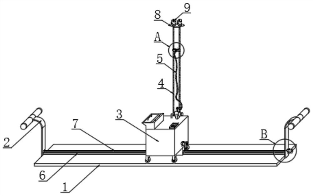
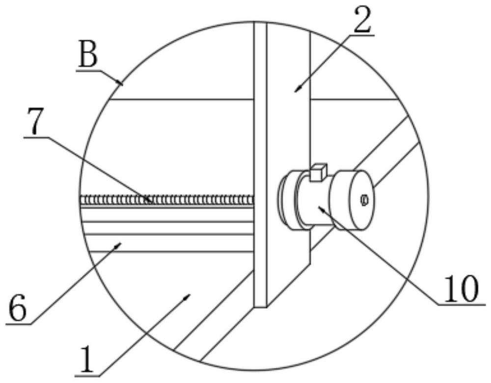
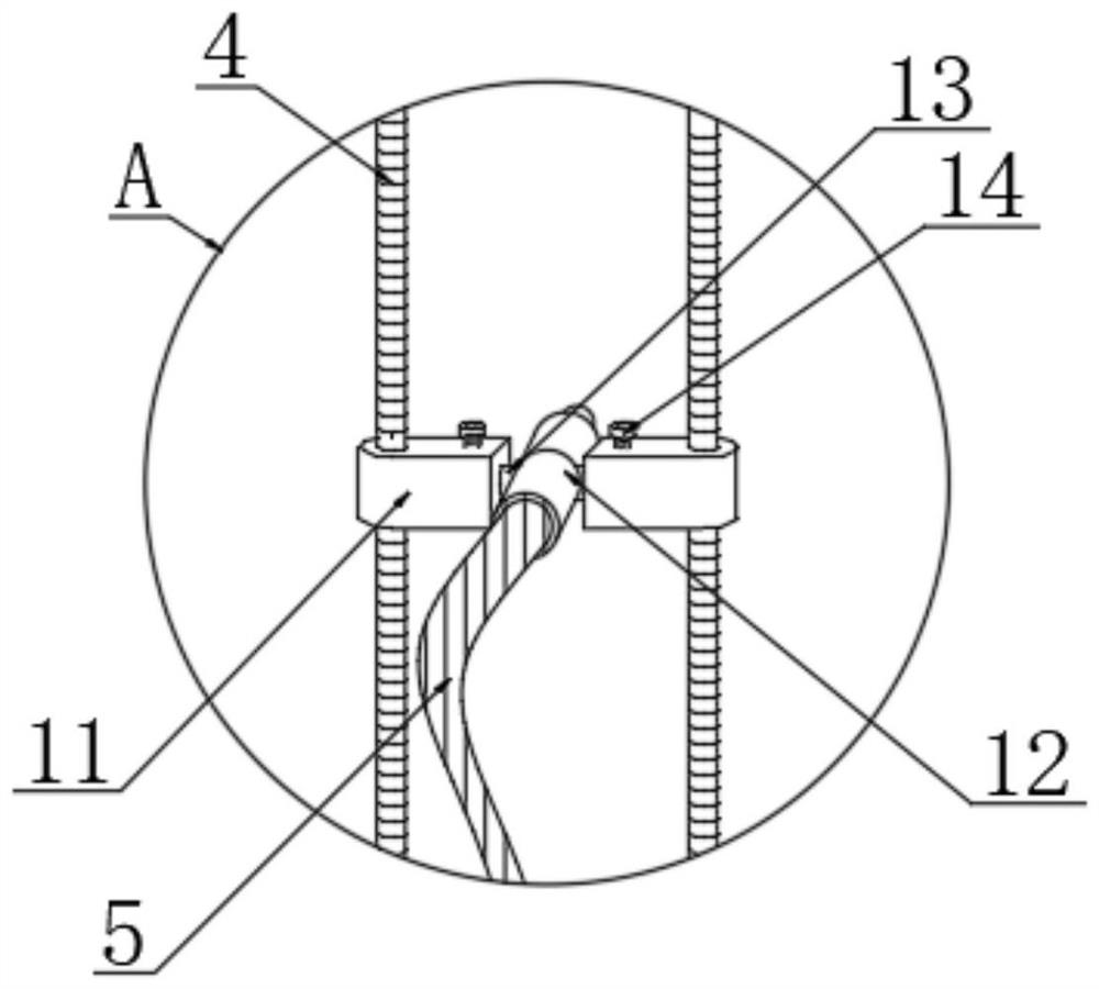
[0021] see Figure 1~5 , in the embodiment of the present invention, an automatic wall surface processing device for architectural decoration engineering, comprising a base plate 1, a handle 2 is welded on one end of the upper surface of the base plate 1, a slide rail 6 is welded on the upper surface of the base plate 1, and the inner lower end of the handle 2 A traverse threaded rod 7 is installed for rotation, a traverse motor 10 is installed on one side of ...


PUM


Abstract

The invention relates to the technical field of wall body machining, in particular to an automatic wall surface machining device for architectural decoration engineering. The device comprises a bottomplate, wherein a handle is welded to one end of the upper surface of the bottom plate, a sliding rail is welded to the upper surface of the bottom plate, a transverse moving threaded rod is rotatablymounted at the lower end of the inner side of the handle, a transverse moving motor is installed at the position, corresponding to the transverse moving threaded rod, of the outer surface of one sideof the handle, a spraying box is slidably installed on the outer surface of the sliding rail, a lifting threaded rod is rotatably installed behind the spraying box, a top plate is installed on the upper surface of the lifting threaded rod, a lifting motor is installed on the upper surface of the top plate, a lifting sliding seat is installed on the outer surface of the lifting threaded rod, a rotating rod is rotatably installed on the inner side of the lifting sliding seat, and a spray head is fixed to the outer surface of the rotating rod. The device is operated automatically, concrete can be prevented from being splashed to an operator, an intelligent control program is set, and spraying is uniform.

Description

technical field [0001] The invention relates to the technical field of wall processing, in particular to an automatic wall processing device for architectural decoration engineering. Background technique [0002] The exterior finish of the wall is divided into indoor wall and outdoor wall. Wall decoration is an integral part of architectural design. Modern indoor walls use color and texture changes to beautify the indoor environment and adjust illumination. Materials with clean and good physical properties to meet various functions. Outdoor walls directly affect the appearance of the building and the appearance of the city. Materials with certain waterproof and weather resistance should be selected according to the use requirements of the building itself and technical and economic conditions. , In some wall treatment, wall concrete spraying treatment. [0003] However, the automated wall concrete spraying currently on the market generally needs to be sprayed manually by hol...

Claims


Application Information

Patent Timeline
Patent Type & Authority Applications(China)
IPC IPC(8): E04F21/08B28C5/08B28C5/14B28C7/16
CPCB28C5/0806B28C5/0856B28C5/14B28C7/163E04F21/08
Inventor 魏爱敏
Owner 魏爱敏
Learn More