
An automatic negative pressure continuous water release device for gas drainage pipeline and its use method

A technology of gas drainage and water discharge device, which is applied in the direction of gas discharge, drainage, mining equipment, etc. It can solve the problems of gas leakage, increase the load of gas drainage pumping stations, and reduce the flammability rate, so as to prevent gas leakage accidents and improve water discharge. Efficiency, gas leakage prevention effect

Active Publication Date: 2022-05-10
CCTEG SHENYANG RES INST
View PDF8 Cites 0 Cited by
  • Summary
  • Abstract
  • Description
  • Claims
  • Application Information

AI Technical Summary

Problems solved by technology

Due to the large amount of water stored in the drainage pipeline, the accumulated sludge in the pipeline will cause resistance to the gas pipeline and increase the load of the gas drainage pumping station, which will cause excessive loss of the pumping station in the long run and reduce the drainage efficiency
In terms of gas utilization such as gas power generation, the gas concentration is too low, the flammability rate is reduced, and the equipment operation efficiency is low
The existing negative pressure automatic water release device has problems such as indirect water discharge and gas leakage when the pipeline stops pumping, resulting in less water discharge, poor water discharge effect and potential safety hazards

Method used


Image

  • An automatic negative pressure continuous water release device for gas drainage pipeline and its use method
  • An automatic negative pressure continuous water release device for gas drainage pipeline and its use method

Examples


Embodiment 1

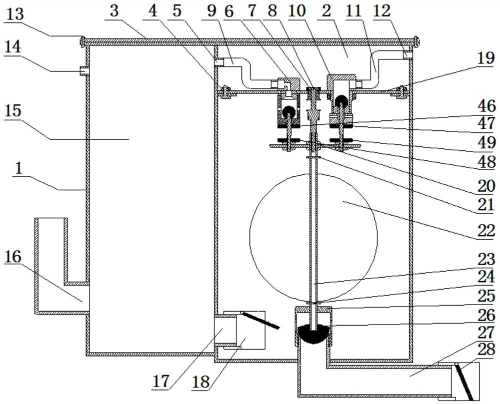
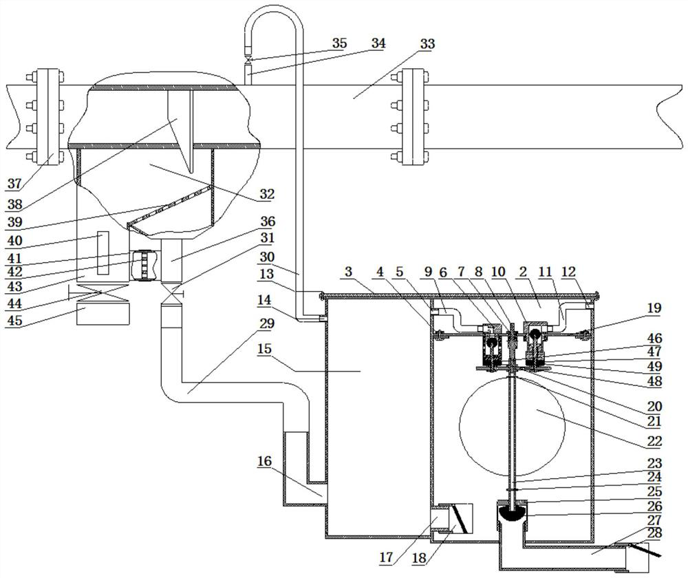
[0028] Such as figure 1 , figure 2As shown, this embodiment proposes a gas drainage pipeline 33 automatic negative pressure continuous water release device, which includes a box body 1, and a partition is provided in the middle of the box body 1, and the partition board divides the inside of the box body 1 into a water discharge tank 2 and a water discharge tank 2. The water storage tank 15, the lower side of the partition is provided with a water storage tank water discharge interface 17 for communicating with the water discharge tank 2 and the internal space of the water storage tank 15, and the water storage tank water discharge interface 17 is provided with a unidirectional conduction for the water in the water storage tank 15 to the water discharge tank 2 The water storage tank discharge valve 18, the side wall corresponding to the water storage tank 15 of the casing 1 is provided with an external negative pressure communication interface 14 and a water inlet pipe interf...

Embodiment 2

[0038] The method of using the automatic negative pressure continuous water discharge device for the gas drainage pipeline 33 proposed in this embodiment uses the automatic negative pressure continuous water discharge device for the gas drainage pipeline 33 in Example 1, and the usage method is specifically as follows:

[0039] The water in the gas drainage pipeline 33 is introduced into the water storage tank 15 through the connecting water pipe 29, the gas drainage pipeline 33 automatically enters the first state of the negative pressure continuous water release device, and the float 22 moves down under the action of gravity, and the water is sealed The rubber ball 26 closes the water discharge interface 27, the vacuum valve body 6 is opened, the water storage tank 15 is communicated with the water discharge tank 2 through the outlet end of the vacuum valve body 6, and the water discharge tank 2 is introduced into negative pressure; the positive pressure regulating valve 10 is...


PUM


Abstract

The invention relates to the field of pipeline water release devices for gas extraction systems, and is an automatic negative pressure continuous water release device for gas extraction pipelines, which includes a water discharge tank and a water storage tank. The water discharge tank and the water storage tank are connected through the water discharge interface of the water storage tank. There is a positive pressure connecting pipe; the bottom of the water discharge tank is provided with a water discharge port, above the water discharge port is a float guide rod, the bottom of the float guide rod is provided with a water discharge sealing rubber ball, the middle part of the float guide rod is provided with a float, and the fixed plate is provided with a vacuum valve body and Positive pressure regulating valve, the valve chamber of the vacuum valve body communicates with the inside of the water discharge tank, the outlet end of the vacuum valve body communicates with the water storage tank, the valve chamber of the positive pressure regulating valve communicates with the atmosphere, and the inlet port of the positive pressure regulating valve Connected with the water tank. The continuous water release device can improve the water discharge efficiency of the automatic negative pressure water release device, and at the same time prevent gas leakage when the pump is stopped. The invention also provides a method for using the automatic negative pressure continuous water release device for the gas extraction pipeline.

Description

technical field [0001] The invention relates to the field of pipeline drainers for gas drainage systems, in particular to an automatic negative pressure continuous drainer for gas drainage pipelines and a use method thereof. Background technique [0002] Gas drainage pipeline automatic negative pressure water release device is an indispensable part of gas drainage pipeline. Due to the large amount of water stored in the drainage pipeline, the accumulated sludge in the pipeline will cause resistance to the gas pipeline and increase the load on the gas drainage pumping station, which will cause excessive loss of the pumping station in the long run and reduce the drainage efficiency. In terms of gas utilization such as gas power generation, the gas concentration is too low, the flammability rate is reduced, and the equipment operation efficiency is low. The existing negative pressure automatic water release device has problems such as indirect water discharge and gas leakage w...

Claims


Application Information

Patent Timeline
IPC IPC(8): E21F16/00E21F7/00E21F17/18E21F17/00
CPCE21F16/00E21F7/00E21F17/18E21F17/00
Inventor 聂永兴李晓光沈维栋徐鹏许健王选亮闫长军闫明玥马强宋宇
Owner CCTEG SHENYANG RES INST
Learn More