Supercharge Your Innovation With Domain-Expert AI Agents!

Electro-hydraulic control system for tractor

A control system and tractor technology, applied in the field of tractors, can solve the problems of electronic control, low degree of intelligence, low operation efficiency, heavy and laborious operation, etc., and achieve the effect of improving the degree of automation, improving comfort and ensuring safety.

Pending Publication Date: 2021-01-22
FIRST TRACTOR
View PDF0 Cites 0 Cited by
  • Summary
  • Abstract
  • Description
  • Claims
  • Application Information

AI Technical Summary

Problems solved by technology

Existing tractor gearboxes mostly use mechanical reversing methods such as meshing sleeves and synchronizers, and the reversing operation is realized by manipulating the reversing fork through a flexible shaft or a lever. The stroke adjustment of the flexible shaft or lever is inconvenient, and the operating efficiency is relatively low. The operation is heavy and laborious. In addition, due to the need to use the clutch in the process of shifting gears, the mechanical clutch control mechanism it uses is also heavy and laborious to operate, which is likely to cause driving fatigue and is difficult to realize driving automation.
Although a few existing tractor gearboxes use wet clutches or continuously variable transmissions and realize tractor reversing through electro-hydraulic control, the cost is high and the technology and structure are complicated
To sum up, the existing tractors equipped with mechanical shift gearboxes have the disadvantages of lack of power assist in the clutch device and heavy and laborious reversing operations, making it difficult to reduce the tractor’s steering force, and the degree of electronic control and intelligence is low, which is not conducive to the realization of mechanical shifting. Intelligent control of geared tractors

Method used


Image

  • Electro-hydraulic control system for tractor
  • Electro-hydraulic control system for tractor
  • Electro-hydraulic control system for tractor

Examples


specific Embodiment approach

[0021] Referring to the accompanying drawings, the specific implementation is as follows:

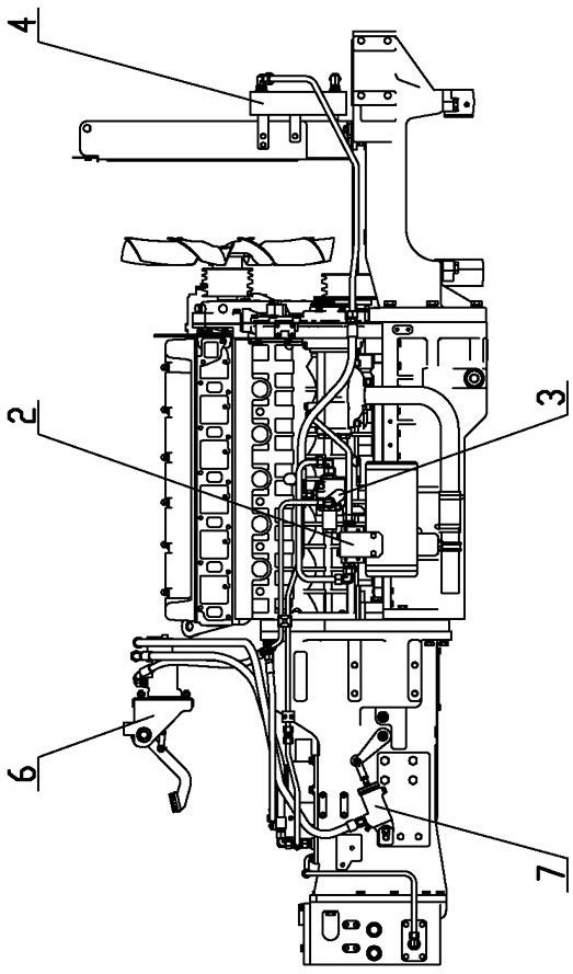
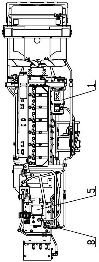
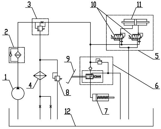
[0022] An electro-hydraulic control system for tractors, including a fuel tank 12, a gear pump 1, an oil filter 2, a single-way stable diverter valve 3, an electro-hydraulic control reversing mechanism 5, a clutch booster pump 6, a clutch booster cylinder 7, and a gear pump 1 Installed in the gear room of the engine, the oil filter 2 and the single-way stable diverter valve 3 are installed on the SCR bracket on the side of the engine, the oil inlet of the gear pump 1 is connected with the oil tank 12, and the oil outlet of the gear pump 1 is connected with the oil filter The oil inlet of oil filter 2 is connected, and the oil outlet of oil filter 2 is connected with the oil inlet of single-way stable diverter valve 3.

[0023] The electro-hydraulic control reversing mechanism 5 is installed on the top of the front box of the gearbox, including two electric proportional pressure reducing...


PUM


Abstract

The invention discloses an electro-hydraulic control system for a tractor. The electro-hydraulic control system comprises an oil tank, a gear pump, an oil filter, a one-way stable diverter valve, an electro-hydraulic control reversing mechanism, a clutch booster pump and a clutch booster oil cylinder; the gear pump, the oil filter and the one-way stable diverter valve are connected in sequence,; the electro-hydraulic control reversing mechanism comprises two electric proportional pressure reducing valves and a reversing oil cylinder; the one-way stable diverter valve is connected with the twoelectric proportional pressure reducing valves respectively; oil cavities in the two sides of a piston of the reversing oil cylinder communicate with the two electric proportional pressure reducing valves respectively and are used for driving the piston of the reversing oil cylinder to move; the one-way stable diverter valve is further connected with the clutch booster pump; the clutch booster pump is connected with the clutch booster oil cylinder; a valve element of the clutch booster pump is connected with a clutch pedal of the tractor through a connecting mechanism; and after the clutch pedal is stepped down from the initial position, the valve element can block an oil inlet and an oil outlet of the clutch booster pump, and the oil pressure can be generated in the positions of the clutch booster oil cylinder and the two electric proportional pressure reducing valves.

Description

technical field [0001] The invention relates to the field of tractors, in particular to an electro-hydraulic control system for tractors. Background technique [0002] Tractors are widely used in our country. In the process of operation, affected by the shape and area of ​​the farmland, there will be multiple forward and reverse switching operations. Existing tractor gearboxes mostly use mechanical reversing methods such as meshing sleeves and synchronizers, and the reversing operation is realized by manipulating the reversing fork through a flexible shaft or a lever. The stroke adjustment of the flexible shaft or lever is inconvenient, and the operating efficiency is relatively low. The operation is heavy and laborious. In addition, because the clutch needs to be used in the gear shifting process, the mechanical clutch control mechanism it adopts is also heavy and laborious to operate, which easily causes driving fatigue and is difficult to realize driving automation. Alth...

Claims


Application Information

Patent Timeline
IPC IPC(8): F16H63/32F16H61/40F16H61/02F16H61/18F16H59/02F15B21/0423
CPCF16H63/32F16H61/40F16H61/0206F16H61/18F16H59/02F15B21/0423
Inventor 赵鑫康健史金钟张举鑫罗明泉刘涛尚彩红李浩扬王文卿段华威
Owner FIRST TRACTOR
Features
  • R&D
  • Intellectual Property
  • Life Sciences
  • Materials
  • Tech Scout
  • Unparalleled Data Quality
  • Higher Quality Content
  • 60% Fewer Hallucinations
Learn More