750kV converter transformer outgoing line cylinder structure and assembling method

A technology for converter transformers and outlet barrels, which is applied in the direction of transformer/inductor coil/winding/connection, transformer/inductor parts, inductor/transformer/magnet manufacturing, etc., which can solve the safety hazards of converter transformers, compression coils to The space of the bushing terminal, the inability to fully guarantee the electrical and mechanical strength of the outlet structure, etc., to achieve the effect of ensuring safe operation, easy disassembly and transportation, and compact structure

Active Publication Date: 2021-01-22
SHANDONG POWER EQUIP
10 Cites 0 Cited by

AI-Extracted Technical Summary

Problems solved by technology

[0003] The 750kV converter transformer on the grid side has a large capacity and high voltage level. In order to meet the requirements of transportation size, the 750kV converter transformer on the grid side adopts an end outlet struc...

Method used

S1, design the first S-type aluminum tube insulation according to converter transformer internal space, the end portion of connecting coil is designed as port round head structure, and port aluminum tube is made into conical thickened tube wall by normal aluminum tube wall thickness, The end is ground into rounded corners, and the internal welding ground seat is connected to the coil in equal positions; the end connecting the pressure equalizing ring is designed as an internal threaded hole structure with increased wall thickness, increasing the wall thickness of the aluminum tube, and four internal threads are provided on the end face The hole is used to install the pressure equalizing ring; the aluminum tube adopts a welded structure as a whole, and the butt weld of the aluminum tube is chamfered at 2*45° before butt welding. The external welding line is smooth, without knots or pits, and the overall grinding is smooth.
S5, design detachable second aluminum tube insulation, the bottom of the second aluminum tube insulation is inserted in the insulating tube and the pressure equalizing ring tha...

Abstract

The invention relates to a 750kV converter transformer outgoing line cylinder structure and an assembly method. The 750kV converter transformer outgoing line cylinder structure comprises a first aluminum pipe insulator, a second aluminum pipe insulator and a cylindrical insulation plug-in structure, wherein the first aluminum pipe insulator is an S-shaped aluminum pipe welding structure with an outer surface provided with crepe paper insulation, one end of the first aluminum pipe insulator is connected with a coil, the other end of the first aluminum pipe insulator is fixedly connected with the cylindrical insulating plug-in structure, the second aluminum pipe insulator is a cylindrical aluminum pipe welding structure with an outer surface provided with a crepe paper insulator, one end ofthe second aluminum pipe insulator is fixedly connected with a voltage-sharing ball, the shape and the size of the outer diameter of the other end of the second aluminum pipe insulator are matched with the shape and the size of the inner diameter of the cylindrical insulating plug-in structure, and the second aluminum pipe insulator is inserted into the cylindrical insulating plug-in structure tobe tightly attached to and in contact connection with the cylindrical insulating plug-in structure. According to the invention, good electrical performance and mechanical performance of the outgoing line structure are ensured, and safe operation of the outgoing line structure is ensured; and the outgoing line cylinder is reliable in structure and convenient to install, the end structure is convenient to disassemble and transport, and it is guaranteed that the size of the outgoing line structure can meet the transportation requirement.

Application Domain

Transformers/inductances coils/windings/connectionsCoils manufacture

Technology Topic

Crêpe paperPipe welding +5

Image

  • 750kV converter transformer outgoing line cylinder structure and assembling method
  • 750kV converter transformer outgoing line cylinder structure and assembling method
  • 750kV converter transformer outgoing line cylinder structure and assembling method

Examples

  • Experimental program(1)

Example Embodiment

[0027] Embodiments of the present invention will be described in detail below in conjunction with the accompanying drawings.
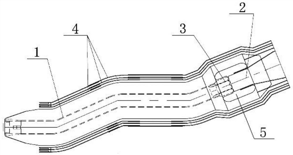
[0028] like figure 1 Shown is a cross-sectional view of the structure of the outlet barrel of the embodiment of the present invention. A 750kV converter transformer outlet barrel structure, including: first aluminum tube insulation 1, second aluminum tube insulation 2, cylindrical insulating plug structure (composed of insulating barrel 3, voltage equalizing ring 5), insulating assembly structure 4 .
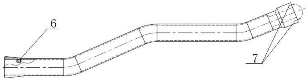
[0029] like figure 2 Shown is a cross-sectional view of the first aluminum tube insulation of the embodiment of the present invention. The first aluminum tube insulation 1 is an S-shaped aluminum tube welded structure with crepe paper insulation on the outer surface, and the length and shape are suitable for the inner space of the transformer; one end of the first aluminum tube insulation 1 is connected to the coil, and the other end is connected to the circle. The cylindrical insulating plug structure is fixedly connected. The first aluminum tube insulation 1 is connected to the end of the coil part ( figure 2 The left end of the center) is a port round head structure, and the aluminum tube at the port is made of a tapered thickened tube wall by the normal aluminum tube wall thickness ( figure 2 The left end of the center has shading, the tapered structure is to match the coil molding), and the end is polished into rounded corners; the internal welding ground seat 6 is connected to the coil in equal positions.
[0030] The other end of the first aluminum pipe insulation 1 ( figure 2 The right end in the middle) is a threaded hole structure for increasing the wall thickness, which increases the wall thickness of the end of the aluminum pipe, and four internal threaded holes 7 are arranged on the end surface for installing the pressure equalizing ring 5.
[0031] like image 3 Shown is a cross-sectional view of the pressure equalizing ring of the embodiment of the present invention; as Figure 4 Shown is a top view of the pressure equalizing ring of the embodiment of the present invention. The pressure equalizing ring 5 is made of aluminum tube material, the end is polished and smooth, and 2mm sulfate pulp is hung on the outside. The inner wall of the pressure equalizing ring 5 is provided with a first inner convex ring 8, and the inner diameter of the first inner convex ring 8 is slightly smaller than the inner diameter of the pressure equalizing ring 5 (2mm difference); the purpose of setting the first inner convex ring 8 is that the first inner convex ring 8 The inner diameter of the inner convex ring 8 is not hung with kraft pulp, so that after hanging 2 mm of kraft pulp on the outside of the pressure equalizing ring 5, the inner diameter of the entire pressure equalizing ring 5 is a flat structure. On the side of the first inner convex ring 8 close to the first aluminum tube insulation 1, a second inner convex ring 9 is arranged, and the inner diameter of the second inner convex ring 9 is smaller than the inner diameter of the first inner convex ring 8; Four first bolt holes 10 are arranged on the end face of 9 , and the positions and sizes of the first bolt holes 10 are matched with the internally threaded holes 7 .
[0032] In order to further improve the insulation performance of the outlet barrel structure, an insulating barrel 3 is provided between the second inner convex ring 9 and the first aluminum tube insulation 1 . like Figure 5 Shown is a cross-sectional view of the insulating cylinder of the embodiment of the present invention; as Image 6 Shown is the left side view of the insulating cylinder of the embodiment of the present invention. The insulating cylinder 3 is a barrel-shaped structure, made of hot-pressed polyester resin plastic, the outer diameter of the insulating cylinder 3 is slightly smaller than the inner diameter of the first aluminum tube insulation 1; one end of the insulating cylinder 3 is inserted into the first aluminum tube insulation 1 , the other end is provided with an outer convex ring 12, the outer diameter of the outer convex ring 12 is slightly smaller than the inner diameter of the pressure equalizing ring 5, four second bolt holes 11 are arranged on the end face of the outer convex ring 12, and the second bolt holes 11 adopt a counterbore structure. Insert one end of the insulation cylinder 3 into the inner diameter of the first aluminum tube insulation 1, install the pressure equalizing ring 5 on the outside of the first aluminum tube insulation 1, and pass the hexagonal screw 13 through the first bolt hole 10 of the pressure equalization ring 5 and the insulation cylinder 3 The second bolt hole 11 of the first aluminum tube insulation 1 is tightened through the internal thread hole 7 of the first aluminum tube insulation 1 to realize the tightness of the first aluminum tube insulation 1 and the cylindrical insulating plug structure (composed of the insulating cylinder 3 and the pressure equalizing ring 5). Fixed connection. like Figure 7 Shown is a cross-sectional view of the first aluminum tube insulation assembly insulation cylinder and pressure equalizing ring according to the embodiment of the present invention. After fastening the connection, wrap the insulation with crepe paper, and the crepe paper insulation at the 5th place of the grading ring is properly thickened.
[0033] like Figure 8 Shown is a cross-sectional view of the second aluminum tube insulation of the embodiment of the present invention. The second aluminum tube insulation 2 is a cylindrical aluminum tube welded structure with crepe paper insulation on the outer surface, one end of the second aluminum tube insulation 2 is fixedly connected to the pressure equalizing ball, and the other end of the second aluminum tube insulation 2 The shape and size of the outer diameter are adapted to the shape and size of the inner diameter of the cylindrical insulating plug-in structure, and the cylindrical insulating plug-in structure is inserted into the cylindrical insulating plug-in structure for close contact and connection. The second aluminum tube insulation 2 is composed of the first section aluminum tube 15, the second section aluminum tube 16, the third section aluminum tube 17, and the fourth section aluminum tube 18 whose diameters are successively smaller. The tube 15, the third section of aluminum tube 17, and the fourth section of aluminum tube 18 are cylindrical, the second section of aluminum tube 16 is funnel-shaped, and its cross-sectional surface is a trapezoidal structure; the fourth section of aluminum tube 18 is inserted into the insulating cylinder 3 , the first section of aluminum pipe 15 is connected to the equalizing ball. Set the corrugated paper insulation 14 on the outside of the first section of aluminum tube 15, the second section of aluminum tube 16, the third section of aluminum tube 17, and the fourth section of aluminum tube 18, and the corrugated paper insulation 14 at the end connected to the pressure equalizing ball is the thickest 1. The crepe paper insulation 14 inserted into one end of the cylindrical insulating plug structure is the thinnest; the thickness of the crepe paper insulation 14 is adjusted according to different parts, ranging from 5mm to 75mm. Insert the second aluminum tube insulation 2 into the pressure grading ring 5 and the insulating cylinder 3, the crepe paper insulation 14 of the second aluminum tube insulation 2 is in close contact with the inner diameter of the pressure grading ring 5 and the insulating cylinder 3, and the first aluminum The tube insulation 1 and the second aluminum tube insulation 2 are plugged together to form a complete 750kV converter transformer outlet barrel structure.
[0034] In order to further enhance the insulation strength of the wire outlet barrel structure, an insulating assembly structure 4 is provided on the surrounding surface of the wire outlet barrel structure. The insulating assembly structure 4 is formed by bonding three-layer molded parts and stays, the three-layer molded parts are a full circle and divided into two parts, and the stays are bonded between the paper tubes to play a fixing role. An insulating assembly is formed by the insulating assembly structure 4 for installation inside a transformer.
[0035] The assembly method of the outlet barrel structure of the 750kV converter transformer, which uses the aforementioned outlet barrel structure, includes the following steps:
[0036] S1. According to the internal space of the converter transformer, the S-shaped first aluminum tube is designed for insulation. The end of the connecting coil is designed as a port round head structure. The port aluminum tube is made of a normal aluminum tube wall thickness into a tapered thickened tube wall, and the end is ground. Rounded corners, the internal welding ground seat and the coil are connected in equal positions; the end of the connecting pressure equalizing ring is designed as an internally threaded hole structure with increased wall thickness, increasing the wall thickness of the aluminum tube, and four internally threaded holes are provided on the end surface for Install the pressure equalizing ring; the aluminum tube as a whole adopts a welded structure, and the butt weld of the aluminum tube is chamfered at 2*45° before butt welding. The external welding line is smooth, without knots or pits, and the overall grinding is smooth.
[0037] S2. Design a pressure equalizing ring, which is made of aluminum tube material, and the end is polished smoothly, and the first bolt hole for insulated connection with the first S-shaped aluminum tube is arranged inside. The equalizing ring is used for the connection of the S-type first aluminum tube insulation and the detachable second aluminum tube insulation.
[0038] S3. Design an insulating cylinder. One end of the insulating cylinder is provided with an outer convex ring, and a second bolt hole is arranged on the outer convex ring. The second bolt hole adopts a counterbore structure.
[0039] S4. Insert the end of the insulating cylinder without the outer convex ring into the first S-shaped aluminum tube for insulation, install the pressure equalizing ring, and pass the hexagonal screw through the first bolt hole on the pressure equalizing ring and the second bolt hole on the insulating cylinder. Fasten the connection through the four internal threaded holes on the S-type first aluminum tube insulation; after the fastening connection, wrap the 50mm insulation with crepe paper (the diameter of the aluminum tube is increased by 100mm), and the pressure equalizing ring is properly thickened, and the connecting coil is matched The coil formers are made in a conical configuration.
[0040] S5. Design a detachable second aluminum tube insulation. The lower part of the second aluminum tube insulation is inserted into the insulating cylinder and pressure equalizing ring that are fixed with the first aluminum tube insulation to form a complete outlet barrel structure; the second aluminum tube insulation The upper part is connected with the pressure equalizing ball by bolts. The second aluminum tube insulation is designed as a plug-in structure, which is easy to install and solves the problem of transportation.
[0041] S6. In order to strengthen the insulation strength of the outlet barrel structure, a 3-layer molded part (a full circle is divided into two parts) and a stay is bonded and formed on the outside of the outlet barrel structure (the stay is bonded between the paper tubes to play a fixing role) , forming an insulating assembly for installation inside a transformer. Using the insulating assembly structure can reduce the distortion field strength and increase the insulation margin, and the multi-layer insulating molded parts are provided with insulating stays between each layer of molded parts to improve its mechanical strength. The molded parts can divide the oil gap and increase creepage distance, thereby effectively reducing the field strength at that location.
[0042] The middle position of the insulating assembly structure is designed to be a structure perpendicular to the iron core, which is convenient to fix on the clamp with a clamp device. The lower connection coil part of the insulating assembly structure adopts slotted stays, and is equipped with a tapered opening, which is convenient for plug-in installation with the coil outlet paper tube.
[0043] Finally, it should be noted that the above examples are only specific implementations of the present invention, and are used to illustrate the technical solutions of the present invention, rather than limit them, and the protection scope of the present invention is not limited thereto. Those skilled in the art should understand that: any person familiar with the technical field within the technical scope disclosed in the present invention can modify the technical solutions described in the foregoing embodiments or can easily think of changes, or modify some of the technical features. Equivalent replacement; and these modifications, changes or replacements do not make the essence of the corresponding technical solution deviate from the spirit and scope of the technical solution of the embodiment of the present invention, and should be covered within the protection scope of the present invention.

PUM

no PUM

Description & Claims & Application Information

We can also present the details of the Description, Claims and Application information to help users get a comprehensive understanding of the technical details of the patent, such as background art, summary of invention, brief description of drawings, description of embodiments, and other original content. On the other hand, users can also determine the specific scope of protection of the technology through the list of claims; as well as understand the changes in the life cycle of the technology with the presentation of the patent timeline. Login to view more.

Similar technology patents

Reliably connected door holder

InactiveCN1584271Areliable connectionSolve unreliable connection
Owner:王小明

Water heating unit with ground structure

Owner:SUZHOU XINYE ELECTRONICS

Classification and recommendation of technical efficacy words

  • reliable connection
  • compact structure

Smart home system based on internet of things cloud computing

Owner:中国联合网络通信有限公司物联网研究院

Bionic underwater chelonian robot

InactiveCN101134500ACloselycompact structure
Owner:HARBIN ENG UNIV

Precision vibration damping and locating device

InactiveCN1724892AAccurate positioningcompact structure
Owner:SHANGHAI MICRO ELECTRONICS EQUIP (GRP) CO LTD
Why Eureka
Try Eureka