Eureka AIR delivers breakthrough ideas for toughest innovation challenges, trusted by R&D personnel around the world.

Battery connector protection device of electric automobile and electric automobile

A technology of battery connectors and protective devices, which is applied in the direction of batteries, electrochemical generators, battery pack components, etc., and can solve problems such as increased thermal effects of high-voltage plug-ins, contact surface wear, and increased contact resistance.

Pending Publication Date: 2021-01-22
XUZHOU XUGONG AUTOMOBILE MFG CO LTD
View PDF4 Cites 1 Cited by
  • Summary
  • Abstract
  • Description
  • Claims
  • Application Information

AI Technical Summary

Problems solved by technology

The dust, water mist and salt mist in the air will stick to the metal conductor of the battery connector in an open environment, which will cause the contact surface of the high-voltage connector conductor to wear, the contact gap will increase, the surface will be dirty, oxidized and electrochemically corroded And other problems, which in turn lead to an increase in contact resistance, and the thermal effect of the high-voltage plug-in during high-rate charge and discharge at the vehicle end and battery assembly end is greatly increased, resulting in energy waste, low power utilization, and severe heat generation of plug-ins, cables, and battery assemblies. Serious problems such as reduced lifespan or even plug-in ablation, cable fire, battery burning or severely reduced battery life, high-temperature thermal runaway of the battery cell, or vehicle unusable due to limited discharge power, etc., will affect the vehicle's operating function, efficiency, life, and cost. serious safety hazard

Method used


Image

  • Battery connector protection device of electric automobile and electric automobile
  • Battery connector protection device of electric automobile and electric automobile
  • Battery connector protection device of electric automobile and electric automobile

Examples


Embodiment Construction

[0026] The following will clearly and completely describe the technical solutions in the embodiments of the present invention with reference to the accompanying drawings in the embodiments of the present invention. Obviously, the described embodiments are only some, not all, embodiments of the present invention. The following description of at least one exemplary embodiment is merely illustrative in nature and in no way taken as limiting the invention, its application or uses. Based on the embodiments of the present invention, all other embodiments obtained by persons of ordinary skill in the art without creative efforts fall within the protection scope of the present invention.

[0027] The relative arrangements of components and steps, numerical expressions and numerical values ​​set forth in these embodiments do not limit the scope of the present invention unless specifically stated otherwise. At the same time, it should be understood that, for the convenience of descriptio...


PUM


Abstract

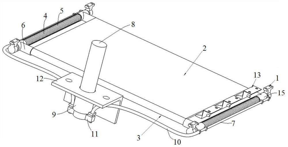
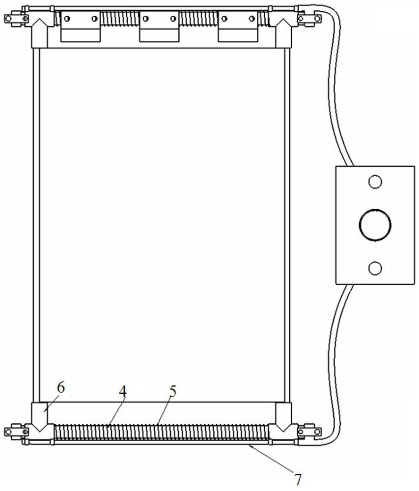
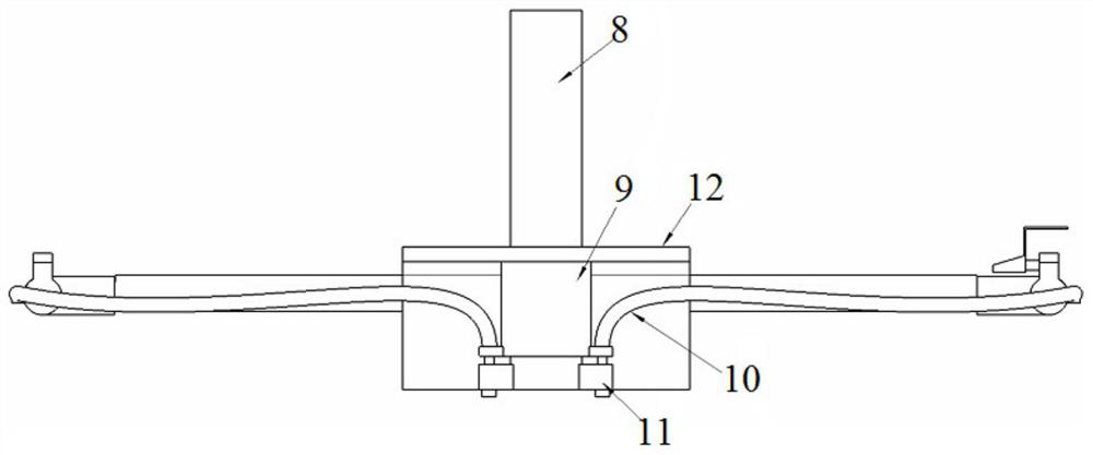
The invention discloses a battery connector protection device of an electric automobile and the electric automobile. The battery connector protection device of the electric automobile comprises a battery support assembly and a protection cover plate, the battery support assembly comprises a battery support used for supporting a battery and a driving part arranged on the battery support, and the driving part is configured to act under the pressure of the battery. The protection cover plate is arranged on one side of the battery support and located above the battery connector, a first side edgeof the protection cover plate is arranged close to the battery support, and a second side edge, far away from the battery support, of the protection cover plate is driven by the driving part to be close to or far away from the first side edge so that the protection cover plate can stretch out and draw back. When the battery is placed on the battery support, the driving part drives the protection cover plate to retract so as to expose the battery connector; when the battery leaves the battery support, the protection cover plate extends to enable the battery connector to be covered. When the battery needs to be replaced, the battery which runs out of power needs to be dismounted, and the protection cover plate extends to enable the battery connector to be covered.

Description

technical field [0001] The invention relates to the field of electric vehicles, in particular to a battery connector protection device for the electric vehicle and the electric vehicle. Background technique [0002] In order to meet the mileage of electric vehicles, it is usually achieved by increasing the power of the power battery. However, the price of the power battery is extremely expensive. Increasing the power will lead to high vehicle costs, resulting in the failure of vehicle operation to pay back in the short term and affecting vehicle sales. At the same time, too large battery capacity faces a long charging time, and most operating conditions require drivers to shift vehicles without stopping. Simply using a large-power power battery charging method cannot meet the operating needs of the vehicle. It can realize the continuous operation of the vehicle and a longer cruising range. [0003] During the battery replacement process, from the time when the exhausted bat...

Claims


Application Information

Patent Timeline
Patent Type & Authority Applications(China)
IPC IPC(8): H01M50/24H01M50/244H01M50/249
CPCH01M2220/20Y02E60/10
Inventor 高鹏各伟康胡文龙庄明兴
Owner XUZHOU XUGONG AUTOMOBILE MFG CO LTD
Why Eureka
Eureka Blog
Learn More