Motor coil paint dipping equipment

A technology of impregnating paint and coils, which is applied in the field of paint impregnating equipment for motor coils, can solve the problems of paint waste, affecting product quality, and high use limitations, so as to improve the quality of impregnating paint, increase the efficiency of impregnating paint, and facilitate painting Effect

Pending Publication Date: 2021-01-22
宣城坚腾智能传动设备有限公司
View PDF0 Cites 0 Cited by
  • Summary
  • Abstract
  • Description
  • Claims
  • Application Information

AI Technical Summary

Problems solved by technology

[0002] In the process of motor production, the impregnation of motor coils is a relatively important process in the preparation of motor coils. The motor coils after impregnation can not only improve the insulation strength and moisture-proof performance, but also improve their heat resistance and heat dissipation, and can also improve the mechanical properties of insulation. Performance, chemical stability, thermal conductivity, heat dissipation effect and aging delay, the poor effect of dipping paint will directly lead to the quality and safety performance of the motor coil, such as the phenomenon of paint peeling off and bare wires, which will cause inter-turn short circuit, resulting in Potential safety hazards directly affect product quality
Existing motor coil impregnation equipment found during the impregnation process of the motor coil that the impregnation of the motor coil was not complete, the effect was poor, and the service life of the coil was affected, and the paint was wasted seriously, resulting in high use limitations

Method used


Image

  • Motor coil paint dipping equipment
  • Motor coil paint dipping equipment
  • Motor coil paint dipping equipment

Examples


Embodiment Construction

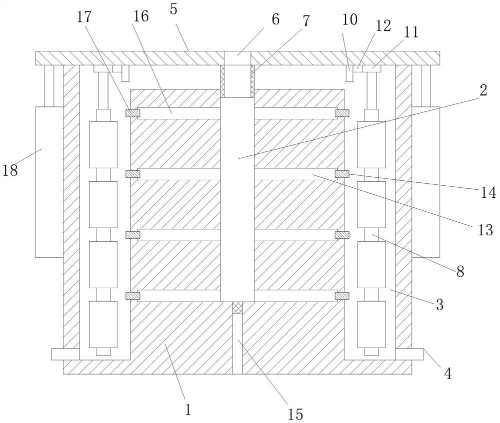
[0017] refer to Figure 1-Figure 3 , the present invention proposes a motor coil impregnating equipment, including a paint impregnating seat 1, a central channel 2 arranged vertically and with an open top is opened in the impregnating paint seat 1, and a plurality of vertically arranged and The dipping channel 3 with an open top, a plurality of dipping channels 3 are arranged circularly around the central channel 2 and the dipping channel 3 communicates with the central channel 2, and a plurality of dipping channels 3 communicated with the plurality of dipping channels 3 are installed on the dipping seat 1 A paint outlet pipe 4, a paint outlet valve is installed on the paint outlet pipe 4.

[0018] The top of the paint dipping seat 1 is equipped with a cover plate 5, and the cover plate 5 is provided with a paint inlet 6. The inside of the cover plate 5 is installed with a paint inlet pipe 7 that communicates with the paint inlet 6 and extends into the central channel 2. The c...


PUM


Abstract

The invention provides motor coil paint dipping equipment which comprises a paint dipping base. A vertically-arranged center channel with the open top end is formed in the paint dipping base, a plurality of vertically-arranged paint dipping channels with the open top ends are further formed in the paint dipping base, the multiple paint dipping channels are annularly arranged around the center channel, and the paint dipping channels communicate with the center channel. A plurality of paint outlet pipes which are respectively communicated with the plurality of paint dipping channels are arrangedon the paint dipping base, and paint outlet valves are arranged on the paint outlet pipes; a cover plate is installed at the top end of the paint dipping base in a matched mode, a paint inlet is formed in the cover plate, a paint inlet pipe which is communicated with the paint inlet and extends into the center channel is installed on the inner side of the cover plate, and a plurality of coil fixing frames which extend into the multiple paint dipping channels respectively are further installed on the inner side of the cover plate. A driving mechanism for driving the plurality of coil fixing frames to rotate in the plurality of paint dipping channels respectively is mounted on the cover plate. The paint dipping equipment is high in paint dipping efficiency and thorough in paint dipping, paint can be stirred through rotation of the coil fixing frame, flowing of the paint is accelerated, and painting of the coil is facilitated.

Description

technical field [0001] The invention relates to the technical field of motor production, in particular to a motor coil dipping equipment. Background technique [0002] In the process of motor production, the impregnation of motor coils is a relatively important process in the preparation of motor coils. The motor coils after impregnation can not only improve the insulation strength and moisture-proof performance, but also improve their heat resistance and heat dissipation, and can also improve the mechanical properties of insulation. Performance, chemical stability, thermal conductivity, heat dissipation effect and aging delay, the poor effect of dipping paint will directly lead to the quality and safety performance of the motor coil, such as the phenomenon of paint peeling off and bare wires, which will cause inter-turn short circuit, resulting in Potential safety hazards directly affect the quality of products. Existing motor coil impregnation equipment found during the i...

Claims


Application Information

Patent Timeline
Patent Type & Authority Applications(China)
IPC IPC(8): H02K15/12
CPCH02K15/12
Inventor 王光军王军峰王建锋陆富贵张国扬
Owner 宣城坚腾智能传动设备有限公司
Why Eureka
Try Eureka