
Blackboard board cutting device with auxiliary locating function

An auxiliary positioning and functional technology, applied in the direction of feeding devices, clamping devices, sawing components, etc., can solve problems such as difficult operation, low efficiency, and potential safety hazards, so as to prevent wood chips from floating and reduce workload Effect

Active Publication Date: 2021-01-26
NANJING HANXIYUE AUTOMATION TECH CO LTD
View PDF20 Cites 6 Cited by
  • Summary
  • Abstract
  • Description
  • Claims
  • Application Information

AI Technical Summary

Problems solved by technology

[0004] In order to overcome the disadvantages of manually pushing wooden boards for cutting, the operation is difficult, the efficiency is not high, and there are potential safety hazards, the technical problem to be solved is: to provide a machine that does not need manual pushing, automatically pushes, clamps and cuts, and ensures safety. Blackboard wood cutting device with auxiliary positioning function

Method used


Image

  • Blackboard board cutting device with auxiliary locating function
  • Blackboard board cutting device with auxiliary locating function
  • Blackboard board cutting device with auxiliary locating function

Examples


Embodiment 1

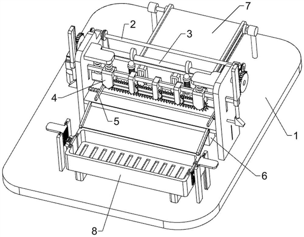
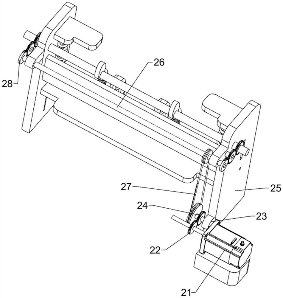
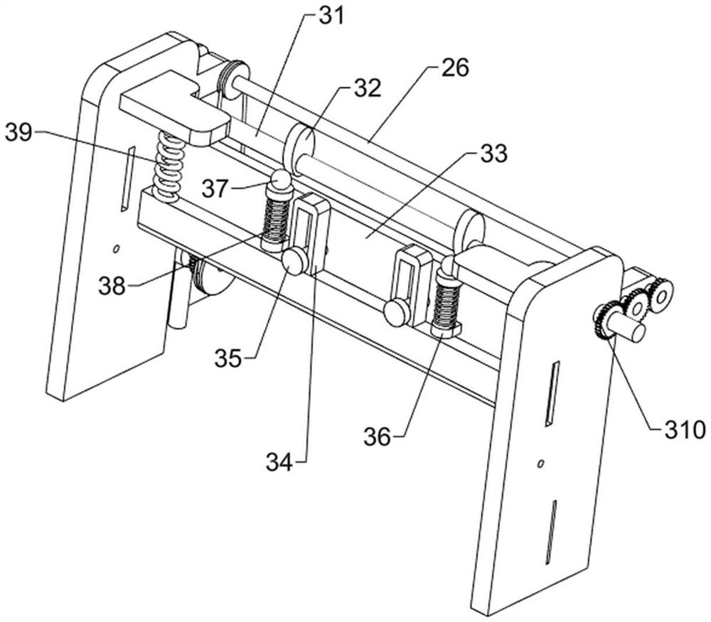
[0058] A blackboard plank cutting device with auxiliary positioning function, such as Figure 1 to Figure 3 As shown, it includes a base 1 , a driving mechanism 2 and a positioning mechanism 3 , the middle side of the top of the base 1 is connected with the driving mechanism 2 , and the driving mechanism 2 is connected with the positioning mechanism 3 .

[0059] The driving mechanism 2 includes a servo motor 21, a first missing gear 22, a first fixed rod 23, a first gear 24, a fixed frame 25, a first rotating shaft 26, a first transmission assembly 27 and a second missing gear 28, and the top of the base 1 The left side is provided with a servo motor 21, the output shaft of the servo motor 21 is connected with a first missing gear 22, the top of the base 1 is provided with a first fixed rod 23, and the right side of the first fixed rod 23 is connected with a first gear 24 in a rotational manner , the first gear 24 meshes with the first missing gear 22, and the middle side of t...

Embodiment 2

[0063] On the basis of Example 1, such as Figure 4 to Figure 7 As shown, a cutting mechanism 4 is also included, and the cutting mechanism 4 includes a third missing gear 41, a slide bar 42, a rack bar 43, a second fixed block 44 and a cutting assembly 45, and the two ends of the second rotating shaft 31 are connected with The third gear 41 is missing, a slide bar 42 is slidably connected between the left and right sides of the fixed frame 25, the left and right sides of the top of the slide bar 42 are connected with a rack bar 43, and the slide bar 42 is connected with five second fixed blocks 44 A cutting assembly 45 is rotatably connected between the lower parts of the second fixing block 44 , and the tops of the second fixing blocks 44 on the left and right sides are elastically connected to the inner wall of the fixing frame 25 .

[0064] Also includes a clamping mechanism 5, the clamping mechanism 5 includes a push block 51, an inclined block 52 and a third spring 53, t...


PUM


Abstract

The invention relates to a board cutting device, and especially relates to a blackboard board cutting device with an auxiliary locating function. According to the blackboard board cutting device withthe auxiliary locating function, manual pushing is not needed, automatic pushing, clamping and cutting are carried out through a machine, and the safety is guaranteed. The blackboard board cutting device with the auxiliary locating function comprises a base and a locating mechanism, wherein a driving mechanism is connected to the middle side of the top of the base; and the locating mechanism is connected to the driving mechanism. By arranging the driving mechanism, all mechanisms behind are driven to work, manual operation is not needed, and the workload is reduced; by arranging the conveyingmechanism, a board is driven to automatically move forwards to be cut; and through the locating mechanism and the clamping mechanism, the moving board is clamped and fixed, and cutting is cooperated.

Description

technical field [0001] The invention relates to a wood board cutting device, in particular to a blackboard wood board cutting device with an auxiliary positioning function. Background technique [0002] The blackboard does not specifically refer to the black board surface. In the traditional sense, it is a plane that can be repeatedly written with chalk. The board surface is hard and is mostly used for teaching. Blackboards are generally made of wood or frosted glass. Writing material to write on. [0003] When the manufacturer manufactures the blackboard, the size of the wooden board will be cut first, and then the wooden board will be made into a blackboard after cutting to a certain size. Because the planks are too large, the operation is difficult, and at the same time relying on manual push, there are potential safety hazards. Contents of the invention [0004] In order to overcome the disadvantages of manually pushing wooden boards for cutting, the operation is dif...

Claims


Application Information

Patent Timeline
IPC IPC(8): B27B17/00B27B17/08B27B25/04B27B29/02B27B31/08B27G3/00
CPCB27B17/00B27B17/08B27B25/04B27B29/02B27B31/08B27G3/00
Inventor 严卫华
Owner NANJING HANXIYUE AUTOMATION TECH CO LTD
Learn More