
Turning-milling combined machining center of woodworking lathe

A compound machining center and woodworking lathe technology, which is applied to wood processing equipment, metal processing equipment, grinding machines, etc., can solve the problem of unprocessable asymmetric workpieces, save time for switching machines, avoid repeated positioning errors, and improve positioning progress effect

Inactive Publication Date: 2021-01-26
赣州科匠机电设备有限公司
View PDF7 Cites 2 Cited by
  • Summary
  • Abstract
  • Description
  • Claims
  • Application Information

AI Technical Summary

Problems solved by technology

[0003] Existing milling heads of woodworking lathes generally only have a two-dimensional design, so they can only do some conventional cylindrical surface processing or slotting processing. For special-shaped workpieces, asymmetrical workpieces cannot be processed

Method used


Image

  • Turning-milling combined machining center of woodworking lathe
  • Turning-milling combined machining center of woodworking lathe
  • Turning-milling combined machining center of woodworking lathe

Examples


Embodiment 1

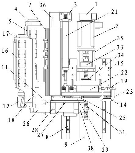
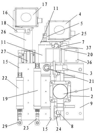
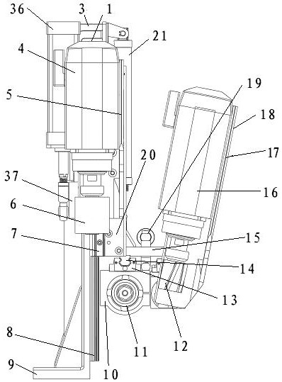
[0019] A woodworking lathe turning and milling compound machining center, including an assembly seat 9, a shaft grinding mechanism, a drilling shaft mechanism, a milling shaft mechanism, and a shaft slide plate 15, the shaft slide plate 15 and the assembly seat 9 are both in an “L” design, and the shaft slide plate 15 The two facades of the assembly seat 9 face away from the warp beam slider 24 and are relatively mobile connected with the shaft slide guide rail 8; On one side, move relatively up and down with shaft slide plate 15; The connection between the shaft slide plate 15 and the assembly seat 9 includes the shaft movement servo motor 2, the servo motor support 35, the screw rod 31, the axle sleeve 33, the thread sleeve 34, the servo motor support 35 is installed on the assembly seat 9, and the shaft movement servo The motor 2 is installed on the servo motor bracket 35, the shaft sleeve 33 is installed on the servo motor bracket 35, the screw rod 31 is connected to the s...

Embodiment 2

[0021] On the basis of Embodiment 1, a buffer cylinder 21 is also included. One end of the buffer cylinder 21 is connected to the shaft slide plate 15, and the other end is connected to the assembly seat 9 for pulling the shaft slide plate 15 so that it can move up and down easily and smoothly.


PUM


Abstract

The invention discloses a turning-milling combined machining center of a woodworking lathe and relates to a woodworking lathe component. A milling head group frame is structurally improved, a group ofrotary knife rests are additionally arranged, and turning of special shapes with different angles and shapes can be conveniently realized. The turning-milling combined machining center of the woodworking lathe comprises an assembly seat, a shaft grinding mechanism, a shaft drilling mechanism, a shaft milling mechanism and a shaft sliding plate, and is characterized in that the shaft sliding plateand the assembly seat are L-shaped; two vertical surfaces of the shaft sliding plate and the assembly seat are in relative movement connection with shaft sliding plate guide rails through shaft sliding blocks in the opposite direction; the shaft grinding mechanism and the shaft drilling mechanism are installed on the shaft sliding plate, and the shaft grinding mechanism is installed on one side of the vertical face of the shaft sliding plate and moves up and down relative to the shaft sliding plate; and the shaft drilling mechanism is installed on the lower side of the shaft sliding plate, and the shaft milling mechanism and the shaft drilling mechanism are installed on the lower side of the plane of the shaft sliding plate in parallel. The turning-milling combined machining center is a numerical control four-axis four-linkage machine tool part combining the functions of a lathe, a drilling machine, a milling machine and a mortising machine.

Description

technical field [0001] The invention relates to a woodworking lathe assembly, in particular to a woodworking lathe turning, milling and turning compound machining center. Background technique [0002] The turning tool of the woodworking lathe in woodworking machinery is a necessary cutting tool for the woodworking lathe. The wooden workpiece is installed between the two thimbles of the woodworking lathe and tightened. When the machine is started, the workpiece rotates, and the turning tool is placed on the knife of the woodworking lathe On the rack, align the workpiece and turn it into parts of different shapes. [0003] The milling heads of existing woodworking lathes generally only have a two-dimensional design, so they can only do some conventional cylindrical surface processing or slotting processing. For special-shaped workpieces, asymmetrical workpieces cannot be processed. Contents of the invention [0004] The object of the present invention is to provide a turnin...

Claims


Application Information

Patent Timeline
Patent Type & Authority Applications(China)
IPC IPC(8): B27C9/04B24B19/24
CPCB24B19/24B27C9/04
Inventor 殷笠
Owner 赣州科匠机电设备有限公司
Learn More