
Wood connecting method utilizing wood dry shrinkage rates

A technology of wood shrinkage and connection method, which is applied to wood processing appliances, manufacturing tools, etc., can solve the problems of poor connection strength, high use cost of connecting parts, and high requirements for drilling accuracy

Active Publication Date: 2021-01-26
海宁普瑞杰玩具开发有限公司
View PDF9 Cites 0 Cited by
  • Summary
  • Abstract
  • Description
  • Claims
  • Application Information

AI Technical Summary

Problems solved by technology

[0005] Aiming at the problems of high drilling precision requirements, high cost of use of connectors, and poor connection strength, the invention provides a wood connection method using wood drying shrinkage

Method used


Image

  • Wood connecting method utilizing wood dry shrinkage rates
  • Wood connecting method utilizing wood dry shrinkage rates
  • Wood connecting method utilizing wood dry shrinkage rates

Examples


Embodiment 1

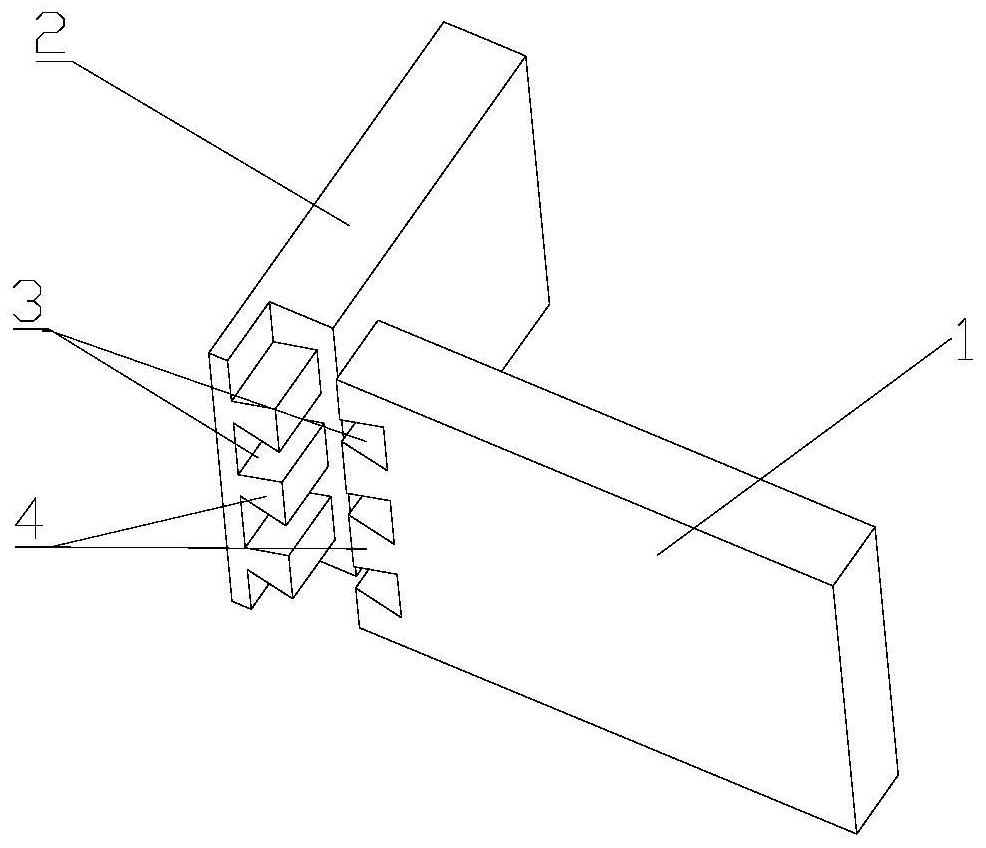
[0030] Such as figure 1 As shown, a wood connection method utilizing wood dry shrinkage, including a first wood piece 1 and a second wood piece 2, the first wood piece 1 is taken from broad-leaved wood (hardwood), and the second wood piece 2 is taken from coniferous wood (cork), the shrinkage rate of the first wood piece 1 is less than the shrinkage rate of the second wood piece 2, comprising the following steps:

[0031] Step 1: drying the first wood piece 1 and the second wood piece 2 respectively to the same moisture content;

[0032] Step 2: Open the same connection port 3 and connection block 4 on the first wood piece 1 and the second wood piece 2, and the shape of the connection port 3 and the connection block 4 is the same;

[0033] Step 3: Connect the first wood piece 1 and the second wood piece 2 with the connection block 4 through the connection port 3;

[0034] Step 4: drying the connected first wood piece 1 and the second wood piece 2 .

[0035] According to the...

Embodiment 2

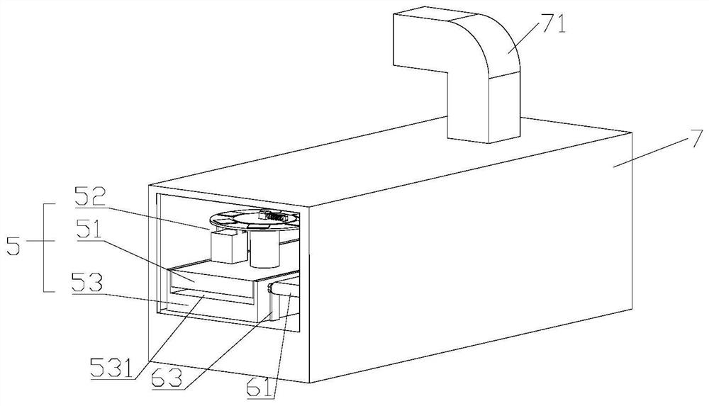
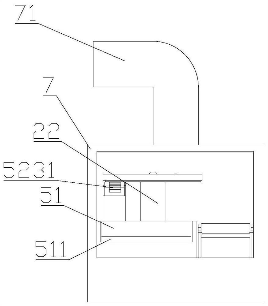
[0037] Such as Figure 2 to Figure 6 As shown, a wood dryer for drying wood pieces connected by the method described in Embodiment 1 includes a drying part 5, and the drying part 5 includes a mounting table 51, a drying table 52 and a base 53 , the top of the base 53 is provided with a chute 531, the installation table 51 is arranged in the chute 531, the drying table 52 is fixedly arranged on the top of the installation table 51, and the drying table 52 includes a drying plate 521, a support column 522 and a transmission part 523, the support column 522 and the transmission member 523 are both arranged between the drying tray 521 and the mounting table 51, the bottom of the drying tray 521 is provided with a transmission groove 5211, and the transmission member 523 includes a transmission wheel 5231 that can cooperate with the transmission groove 5211, The transmission member 523 is connected to the drying plate 521 through the transmission wheel 5231 and the transmission gro...

Embodiment 3

[0043] The difference between this embodiment and Embodiment 2 is that: the drying tray 521 is provided with a sensor 5212 for detecting the moisture content of wood.


PUM


Abstract

The invention relates to the technical field of wood connection, and in particular, to a wood connection method utilizing wood dry shrinkage rates. The method comprises the following steps of providing a first wood piece (1) and a second wood piece (2), drying the first wood piece (1) and the second wood piece (2) with different dry shrinkage rates until moisture contents are consistent, then forming connecting ports (3) in the first wood piece (1) and the second wood piece (2) respectively, properly connecting by the connecting ports (3), and subsequently drying again. As the dry shrinkage rates are different and softwood is larger in dry shrinkage rate and is also larger in deformation degree, a joint of the first wood piece (1) and the second wood piece (2) can be clamped; therefore, the purpose of connection and fixation is achieved; according to the method, the wood is connected and fixed by using the physical characteristics of the wood; the punching and other connecting pieces are not needed; moreover, the wood can be dried by using an original dryer of a factory; and the purpose of cost reduction is achieved.

Description

technical field [0001] The invention relates to the technical field of wood connection, in particular to a wood connection method utilizing wood drying shrinkage. Background technique [0002] At present, the main materials of my country's building structures, such as concrete, steel, and brick masonry, are high-energy-consuming materials. The situation forces us to look for more energy-saving and environmentally friendly building materials. Wood has entered the sight of choice. In western developed countries, wood structures have become The main building form of residential buildings, the large demand for wood also stimulated the development of forestry. While North America is meeting its own needs, it also exports a large amount of timber to other countries, which creates good conditions for the development of modern light wood structure system buildings in my country. There are many connection forms of wood structures, such as bucket arches, mortise and tenon joints, teeth...

Claims


Application Information

Patent Timeline
IPC IPC(8): B27M3/00
CPCB27M3/0066
Inventor 陈毅
Owner 海宁普瑞杰玩具开发有限公司
Learn More