Metal plating mechanism based on electroplating mode

A metal and inner cavity technology, applied in the field of metal plating mechanism based on electroplating, can solve the problems of inconvenient metal extraction, metal cannot be plated, tools are easy to drop accidentally, etc., to improve the quality of plating, convenient The effect of safe extraction

Inactive Publication Date: 2021-01-26
翁荣荣
View PDF0 Cites 0 Cited by
  • Summary
  • Abstract
  • Description
  • Claims
  • Application Information

AI Technical Summary

Problems solved by technology

[0002] The plating of metal materials is the process of plating a thin layer of other metals or alloys on some metal surfaces to play the role of anti-oxidation, improve wear resistance, electrical conductivity, corrosion resistance, etc. During the use of the metal plating mechanism performed by electroplating, after the metal to be plated enters the electrolyte from the air, air bubbles or water films will naturally occur on the surface of the metal, and these air-carrying air bubbles or water films cannot be automatically removed. Cracks, which in turn will cause some areas of the metal surface to be unable to be plated, and ultimately affect the plating quality of the metal. In addition, after the metal plating is completed, it is necessary to manually use tools to remove the plated metal parts in the electrolyte, and tools are used on the way It is easy to accidentally drop into the electrolytic tank, and the user's skin is also easy to come into contact with the electrolyte, which poses a certain safety hazard
[0003] Aiming at the deficiencies of the prior art, the present invention provides a metal plating mechanism based on electroplating, which has the advantages of effectively improving the quality of metal plating and allowing users to conveniently and safely extract the metal after plating. It solves the problem that the general metal plating mechanism based on the electroplating method has average plating quality and it is inconvenient for users to extract the metal after plating.

Method used


Image

  • Metal plating mechanism based on electroplating mode
  • Metal plating mechanism based on electroplating mode
  • Metal plating mechanism based on electroplating mode

Examples


Embodiment Construction

[0021] The following will clearly and completely describe the technical solutions in the embodiments of the present invention with reference to the accompanying drawings in the embodiments of the present invention. Obviously, the described embodiments are only some, not all, embodiments of the present invention. Based on the embodiments of the present invention, all other embodiments obtained by persons of ordinary skill in the art without making creative efforts belong to the protection scope of the present invention.

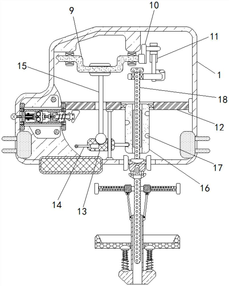
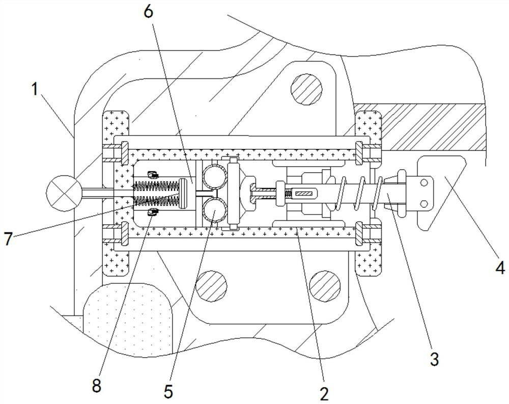
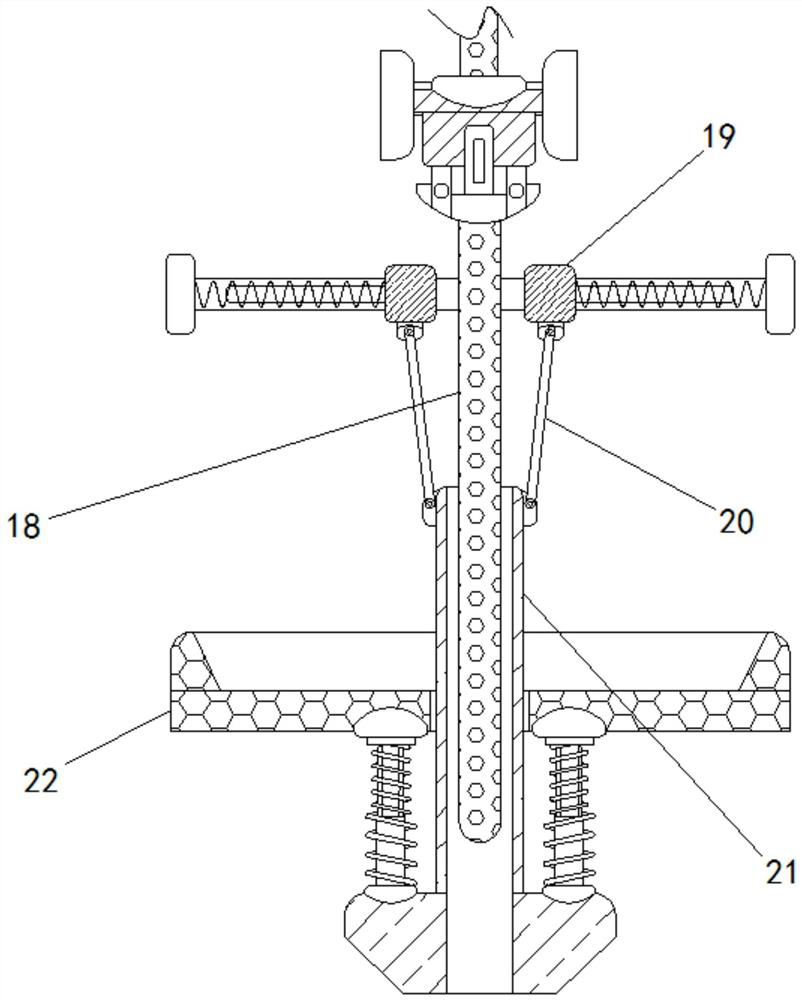
[0022] see Figure 1-4 , a metal plating mechanism based on electroplating, including a housing 1, a warning device is fixedly installed on the left side of the reinforcement shaft 18 at the bottom of the housing 1, and a positioning frame 2 is fixedly installed on the left wall of the inner cavity of the housing 1 , the left part of the positioning frame 2 is fixedly installed with a valve tube extending into the inner cavity of the gas storage tank 6, the va...


PUM


Abstract

The invention relates to the technical field of metal plating, and discloses a metal plating mechanism based on an electroplating mode. The metal plating mechanism comprises a shell, a positioning frame is fixedly mounted on the left wall of an inner cavity of the shell, an elastic rod is slidably connected to the inner cavity of the positioning frame, and a wedge block is fixedly connected to theright end of the elastic rod. An air bag set is fixedly installed on the left wall of the inner cavity of the positioning frame, an air storage groove is formed in the left portion of the positioningframe, and an elastic piston is slidably connected to the right portion of the inner cavity of the air storage groove. According to the metal plating mechanism based on the electroplating mode, a rotating crank, a guide handle and a curved connecting frame are matched to enable a reinforcing shaft to reciprocate up and down, a spherical connecting rod, a sliding block and a rotating cylinder arematched to enable the reinforcing shaft to rotate, bubbles on the surface of plated metal can be broken through the two combined movement modes, and therefore, the metal plating quality is effectivelyimproved, and a user can conveniently and safely extract the plated metal.

Description

technical field [0001] The invention relates to the technical field of metal plating, in particular to a metal plating mechanism based on electroplating. Background technique [0002] The plating of metal materials is the process of plating a thin layer of other metals or alloys on some metal surfaces to play the role of anti-oxidation, improve wear resistance, electrical conductivity, corrosion resistance, etc. During the use of the metal plating mechanism performed by electroplating, after the metal to be plated enters the electrolyte from the air, air bubbles or water films will naturally occur on the surface of the metal, and these air-carrying air bubbles or water films cannot be automatically removed. Cracks, which in turn will cause some areas of the metal surface to be unable to be plated, and ultimately affect the plating quality of the metal. In addition, after the metal plating is completed, it is necessary to manually use tools to remove the plated metal parts in...

Claims


Application Information

Patent Timeline
Patent Type & Authority Applications(China)
IPC IPC(8): C25D17/00C25D21/10C25D21/12C25D17/08G08B21/24
CPCC25D17/00C25D17/08C25D21/10C25D21/12G08B21/24
Inventor 翁荣荣
Owner 翁荣荣
Why Eureka
Try Eureka