Impact-resistant split type hydraulic lifting dam capable of preventing turbulence

A hydraulic lifting dam, impact resistance technology, applied in sustainable biological treatment, water/sludge/sewage treatment, marine engineering, etc. effect of life

Pending Publication Date: 2021-01-26
岭南水务集团有限公司
View PDF0 Cites 0 Cited by
  • Summary
  • Abstract
  • Description
  • Claims
  • Application Information

AI Technical Summary

Problems solved by technology

At present, the common water-retaining surface materials on the market are mainly steel and concrete. The double impact of th

Method used


Image

  • Impact-resistant split type hydraulic lifting dam capable of preventing turbulence
  • Impact-resistant split type hydraulic lifting dam capable of preventing turbulence
  • Impact-resistant split type hydraulic lifting dam capable of preventing turbulence

Examples


Embodiment 1

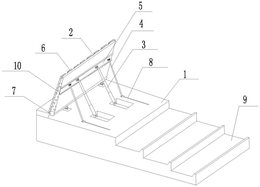
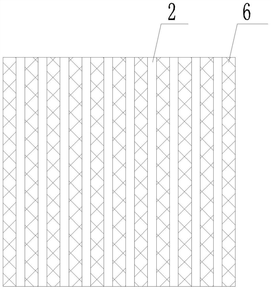
[0034] see figure 1 As shown, the anti-shock split hydraulic lifting dam provided in this embodiment can prevent turbulent flow, including dam body foundation 21, water retaining panel, hydraulic rod 3, drop water energy dissipation system 9, and the water retaining panel connects with the hinge 7 The dam body foundation 21 is connected, and a beam 5 is arranged on the water retaining panel. One end of the hydraulic rod 3 is connected to the beam 5, and the other end is connected to the embedded part of the dam surface. The driving hydraulic rod is set on the dam body foundation 21 on the back of the water retaining panel 3. Lifting oil cylinders are used to adjust the height of the dam surface. The hydraulic lifting dam is composed of multiple split water retaining panels; the dam body foundation 21 is provided with a reserved groove 8 for oil pipelines. When the dam body is in normal operation, a 30cm high water head is allowed to overflow on the dam to form a waterfall land...

Embodiment 2

[0040] In this embodiment, on the basis of the structure of Embodiment 1, the falling water energy dissipation system 9 is further limited, and its structure is the same as that of Embodiment 1, so it will not be repeated in this embodiment.

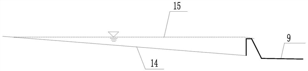
[0041] attached Figure 4 The positions of relevant parameters are illustrated, and the hydraulic calculation method of the multi-level drop in this embodiment is as follows:

[0042] (1) The parameters of the first-stage drop 12 of the drop water energy dissipation system 9 are determined according to the following formula:

[0043]

[0044]

[0045]

[0046]

[0047] δ c1 =(1~2)H 1 (5)

[0048] In the formula, c 1 is the height of the first-level tail sill, in m; H 10 is the water head at the top of the first-level tail sill, in m; H 1 is the water depth at the top of the first-level tail sill, in m; l 1 is the length of the first-level platform, in m; δ c1 It is the length of the top of the first level tail sill, ...


PUM


Abstract

The invention relates to an impact-resistant split type hydraulic lifting dam capable of preventing turbulence. The dam comprises a dam body foundation, water retaining panels, a hydraulic rod and a drop energy dissipation system, wherein the water retaining panels are movably connected with the dam body foundation, impact-resistant composite protection structures are arranged on the front surfaces of the water retaining panels, an oil cylinder for driving the hydraulic rod to lift and lower is arranged on the dam body foundation on the back surfaces of the water retaining panels for adjustingthe height of a dam face, the hydraulic lifting dam is composed of a plurality of split type water retaining panels, and the drop energy dissipation system is located on the back faces of the water retaining panels and comprises multistage stilling ridges. The hydraulic lifting dam has the beneficial effects that by additionally arranging the impact-resistant composite protection structures, theimpact resistance of the water retaining panels is improved, and the service life of the lifting dam is prolonged. When the split type water retaining panels go wrong, the split type water retaining panels can be independently overhauled, and overall operation of the lifting dam is not affected. The multistage stilling ridges can reduce the scouring effect of a water body on the downstream, and can also achieve an aeration effect to increase the content of dissolved oxygen in the water body.

Description

technical field [0001] The invention relates to a river course dam, in particular to an anti-shock split type hydraulic lift dam which can prevent turbulent flow. Background technique [0002] Rivers in mountainous areas have a large gradient, heavy rains are concentrated and intense, the confluence time is short, the water flow is fast, and the rivers are scoured severely; the riverbed is mostly composed of bedrock and pebbles; and the floods come and go quickly, and the dry season often causes the riverbed to be exposed. Further intensified the denudation and weathering of the riverbed. Therefore, in mountainous rivers, especially in scenic river sections with large gradients and serious erosion, a certain degree of water storage should be carried out without affecting the flood discharge of the river to form a water cushion, which can not only slow down the erosion of the river by floods, It can also create a certain landscape. [0003] Therefore, barrages are widely us...

Claims


Application Information

Patent Timeline
IPC IPC(8): E02B7/40E02B7/54E02B8/06E02B8/04C02F7/00
CPCC02F7/00E02B7/40E02B7/54E02B8/045E02B8/06Y02W10/10
Inventor 陈广宇佟镇张烈涛李艳菊裴建全丛海扬
Owner 岭南水务集团有限公司
Why Eureka
Try Eureka