Short-radius controllable trajectory drilling tool

A drilling tool and short-radius technology, which is applied in the field of short-radius controllable trajectory drilling tools, can solve problems such as poor economic benefits, large borehole curvature, and increased difficulty in the construction of well sections, achieving short build-up rates and increased steering stability Effect

Pending Publication Date: 2021-01-26
万晓跃
View PDF0 Cites 8 Cited by
  • Summary
  • Abstract
  • Description
  • Claims
  • Application Information

AI Technical Summary

Problems solved by technology

Because the existing directional drilling technology cannot achieve short-radius steering, it is difficult to develop ultra-thin reservoirs, or it is difficult to create a directional well in the cap rock but requires a large curvature steering after entering the reservoir, or realize branching as much as possible Drilling, or realizing large-angle turns in shallow formations, or sidetracking branch wells in existing wells to realize the production of side well reserves; in the prior art, screw drilling tools with bent joints are usually used to drill branch wells To realize the production of side-hole reserves, the existing data show that the existing screw drilling directional drilling technology and other directional drilling technologies cannot exceed the build-up rate of 15° / 30m
[0006] To sum up, if the wellbore curvature is too large, the existing directional well technology with controllable trajectory cannot be realized; if the wellbore curvature is too small, the build-up section is too long, and the well section in the turning state will generate a large amount of invalid footage. The economic benefit is poor and the operation difficulty of the construction well section is increased. The steering performance and passing performance of other controllable trajectory drilling tools cannot exceed the limit of 18° / 30m, which has the same problems as the screw drilling tools detailed above.

Method used


Image

  • Short-radius controllable trajectory drilling tool
  • Short-radius controllable trajectory drilling tool
  • Short-radius controllable trajectory drilling tool

Examples


Embodiment approach 1

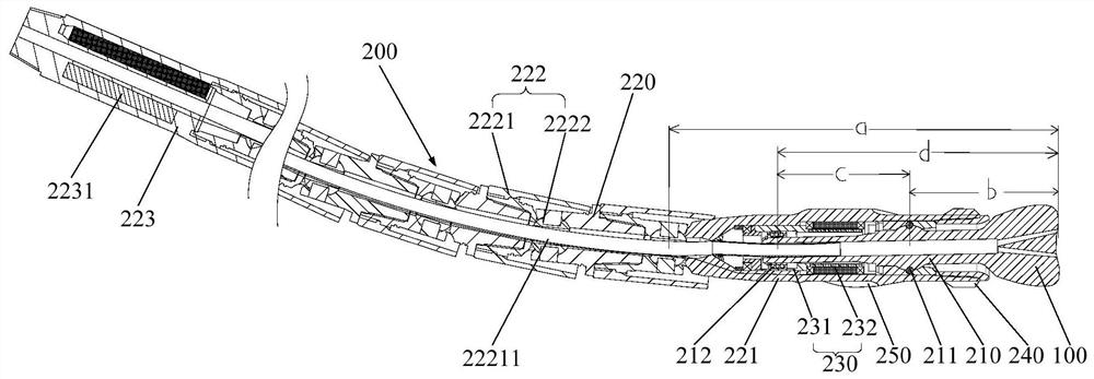
[0072] Such as figure 1 As shown, the offset lever 210 is inserted inside the carrying body 221, the deflection guide mechanism 230 includes an eccentric ring 231, and the carrying body 221 is provided with an electrical actuator 2211, the electrical actuator 2211 is a driving motor 232, and the driving motor 232 ring Set on the outside of the bias lever 210, the eccentric ring 231 is arranged on the top of the drive motor 232 and connected to the rotor output end of the drive motor 232, the drive motor 232 can drive the eccentric ring 231 to rotate, and the eccentric ring 231 and the bias lever 210 are arranged There is a bearing 212, and the rotation of the eccentric ring 231 can drive the bias lever 210 to swing around the controllable weight-on-bit torque deflection transmission mechanism 211 and / or rotate around the axis of the bearing body 221. Specifically, the eccentric ring 231 drives the bias lever 210 The direction of rotation of the rear end of the rear end around ...

Embodiment approach 2

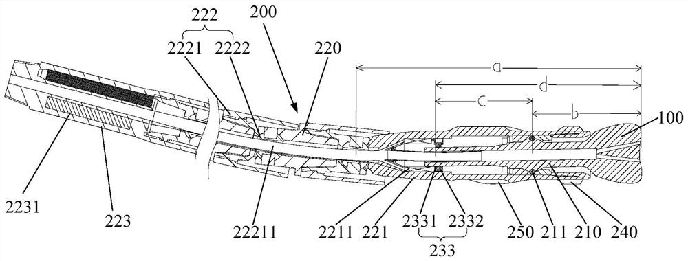
[0075] Such as figure 2 As shown, the bias lever 210 is inserted inside the carrying body 221, and the carrying body 221 is provided with an electrical actuator 2211, the electric actuator 2211 includes a solenoid valve 22111, and the deflection guide mechanism 230 includes at least three groups along the carrying body 221. The driving hydraulic cylinder 233 arranged radially at intervals, the driving hydraulic cylinder 233 includes a cylinder barrel 2331 connected to the side wall of the bearing body 221 and a driving piston 2332 arranged in the cylinder barrel 2331, the driving piston 2332 is connected with a pusher, and the electromagnetic The valve 22111 can periodically drive the driving piston 2332 to move along the radial direction of the bearing body 221, and the driving piston 2332 can periodically drive the pusher to move along the radial direction of the bearing body 221, and the movement of the pusher can drive the bias lever 210 Rotate around the center of the co...

Embodiment approach 3

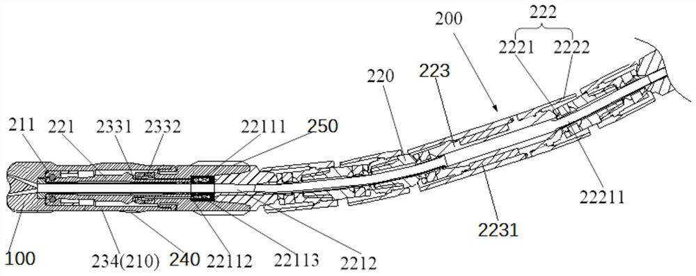
[0078] Such as image 3 and Figure 4 As shown, the bias lever 210 is a hinged sleeve 234, and the deflection guide mechanism 230 is connected to the inner wall surface of the bearing body 221. The deflection guide mechanism 230 includes at least three groups of driving hydraulic cylinders 233 arranged at intervals along the radial direction of the bearing body 221, The driving hydraulic cylinder 233 includes a cylinder 2331 connected to the side wall of the bearing body 221 and a driving piston 2332 arranged in the cylinder 2331. The driving piston 2332 can abut against the inner wall of the hinged sleeve 234, and the bearing body 221 also An electrical actuator 2211 is provided, and a flow channel 2212 is provided inside the carrying body 221. The electrical actuator 2211 includes a plurality of solenoid valves 22111 corresponding to each driving hydraulic cylinder 233. The solenoid valve 22111 has a first passage 22112 and a second passage 22113, the first passage 22112 co...


PUM


Abstract

The invention provides a short-radius controllable trajectory drilling tool. The drilling tool comprises a drill bit and a controllable flexible bit pressure torque transmission tubular column, wherein the controllable flexible bit pressure torque transmission tubular column comprises an offset lever and a plurality of bearing short sections, and the lower end of the offset lever is fixedly connected with the drill bit; every two adjacent bearing short sections are hinged through a bit pressure torque deflection transmission mechanism, the lowermost bearing short section is a bearing body, anda deflection guide mechanism is arranged on the bearing body; the lower portion of the offset lever is hinged to the lower portion of the bearing body through a controllable bit pressure torque deflection transmission mechanism, and a movable gap is formed between the offset lever and the bearing body; and the deflection guide mechanism is arranged in the movable gap and located above the controllable bit pressure torque deflection transmission mechanism, and the deflection guide mechanism can drive the offset lever to swing and/or rotate. According to the short-radius controllable trajectorydrilling tool, deflecting of boreholes of short-extremely-short-radius wells can be achieved, or guiding drilling of extending well sections of the short-extremely-short-radius wells can be achievedthrough short-extremely-short-radius well sections.

Description

technical field [0001] The invention relates to the technical field of drilling, in particular to a short-radius controllable trajectory drilling tool. Background technique [0002] The control of production costs has always been the goal pursued by oil and gas drilling. With the development of unconventional oil and gas fields, the requirements for drilling equipment are getting higher and higher. Automatic, intelligent and efficient drilling technology has become the mainstream of reducing costs and improving efficiency. , In addition, drilling technology also has a large number of applications in the field of geological engineering and mineral development. [0003] At present, the bottom drilling tool assembly of rotary drilling equipment generally controls the deflection performance of the drilling tool through the placement position of different stabilizers or other changes in the relationship between the drilling tool assembly, which can realize the limit deflection ra...

Claims


Application Information

Patent Timeline
Patent Type & Authority Applications(China)
IPC IPC(8): E21B7/06
CPCE21B7/061
Inventor 徐梓辰万晓跃其他发明人请求不公开姓名
Owner 万晓跃
Why Eureka
Try Eureka