Design method for torsional vibration of reciprocating compressor rotor system

A compressor rotor and torsional vibration technology, applied in design optimization/simulation, constraint-based CAD, special data processing applications, etc., can solve problems such as large calculation deviation, poor popularization and applicability, and high model simplification, and achieve improved consistency , Improve calculation accuracy and functional scope, facilitate technology precipitation and upgrade and improve the effect

Pending Publication Date: 2021-01-26
SHENYANG POLYTECHNIC UNIV
View PDF0 Cites 2 Cited by
  • Summary
  • Abstract
  • Description
  • Claims
  • Application Information

AI Technical Summary

Problems solved by technology

There are many limitations in the traditional special-purpose analysis software. In addition to poor popularization and applicability, the traditional calculation method has a high amount of model simplification and relatively large calculation deviations, and can only perform calculations under the critical speed of the rotor without bearing constraints and the simple harmonic load. Kinetic calculation
With the wide application of large-scale general finite element analysis software, the purpose of the present invention is to provide a calculation method based on ANSYS finite element calculation software for the torsional vibration of the reciprocating compressor rotor system, to solve the problem of restricting the reciprocating compressor to multi-row, high-speed The technical bottleneck of development

Method used


Image

  • Design method for torsional vibration of reciprocating compressor rotor system
  • Design method for torsional vibration of reciprocating compressor rotor system
  • Design method for torsional vibration of reciprocating compressor rotor system

Examples


Embodiment Construction

[0039] The following will clearly and completely describe the technical solutions in the embodiments of the present invention with reference to the accompanying drawings in the embodiments of the present invention. Obviously, the described embodiments are only some, not all, embodiments of the present invention. Based on the embodiments of the present invention, all other embodiments obtained by persons of ordinary skill in the art without making creative efforts belong to the protection scope of the present invention.

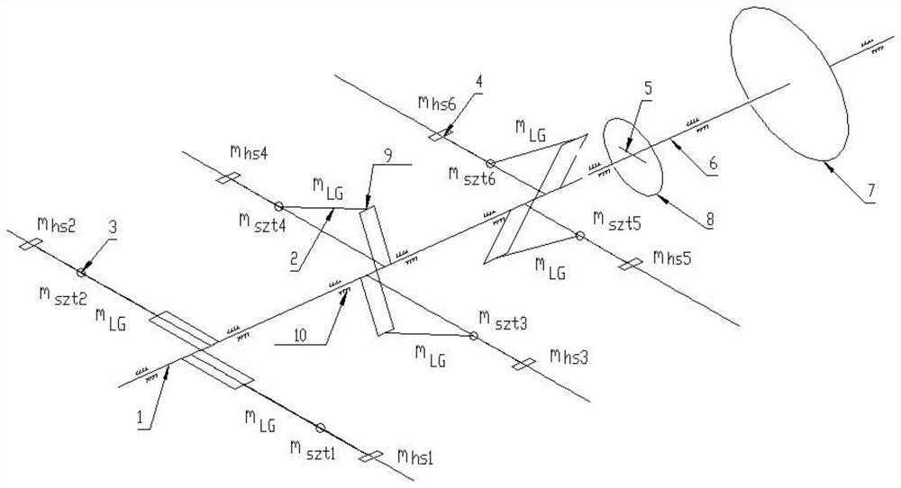
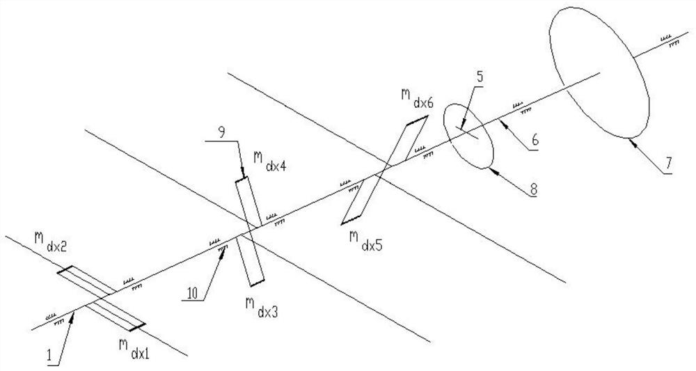
[0040] Please refer to Figures 1-6, the present invention provides a technical solution: a design method for torsional vibration of a reciprocating compressor rotor system, the steps of which are as follows:

[0041] (1) Carry out mass equivalent calculation for the moving parts of the reciprocating compressor, and provide data for the model transformation of the torsional vibration system of the reciprocating compressor rotor system; the moving parts of the re...


PUM


Abstract

The invention discloses a design method for torsional vibration of a reciprocating compressor rotor system, and the method comprises the steps of carrying out the mass equivalent calculation on a moving part of a reciprocating compressor, and providing data for the model conversion of a torsional vibration system of the reciprocating compressor rotor system, wherein the reciprocating compressor moving part for mass equivalent calculation comprises a connecting rod, a crosshead and a piston; and according to the principle that the rotational inertia of the structure is equal, carrying out equivalent processing on a coupler structure, a flywheel and a motor rotor structure of the rotor system, thereby completing the geometric model construction of the reciprocating compressor rotor system comprising a crankshaft, the equivalent coupler, the equivalent flywheel, a motor shaft and a equivalent motor rotor; and using the general ANSYS finite element calculation software for replacing the original special analysis software, so that the calculation precision and the working efficiency of the torsional resonance of the reciprocating compressor rotor system are improved, and the method is not limited by the proprietary technical attribution of reciprocating compressor series products and can be widely applied in the industry.

Description

technical field [0001] The invention relates to the field of rotor dynamics calculation of a reciprocating compressor, in particular to a design method for torsional vibration of a rotor system of a reciprocating compressor. Background technique [0002] The calculation technology of the torsional vibration of the rotor system of the reciprocating compressor is the technical bottleneck restricting the development of the reciprocating compressor to multi-column or high speed. A large number of studies have shown that the more columns of the reciprocating compressor rotor system, the lower the torsional natural frequency of the system, and the easier it is for the unit to resonate; the higher the speed of the reciprocating compressor, the greater the torsional load that causes system resonance, and the easier it is for the unit Resonance occurs. [0003] The calculation of the torsional vibration of the reciprocating compressor rotor system usually uses traditional special an...

Claims


Application Information

Patent Timeline
Patent Type & Authority Applications(China)
IPC IPC(8): G06F30/17G06F30/23G06F111/04G06F119/14
CPCG06F30/17G06F30/23G06F2111/04G06F2119/14
Inventor 许增金王世杰赵东升孟文惠张士永连东辉李福宝齐荣琴袁本中
Owner SHENYANG POLYTECHNIC UNIV
Why Eureka
Try Eureka