
Cable crushing copper-plastic separation device

A separation device, copper-plastic technology, applied in circuits, electrical components, electronic waste recycling and other directions, can solve the problems of low separation efficiency, safety and hidden dangers of hook type cable cutters, and achieve the effect of improving separation efficiency

Active Publication Date: 2021-01-26
安徽省金鸿电线电缆有限公司
View PDF5 Cites 2 Cited by
  • Summary
  • Abstract
  • Description
  • Claims
  • Application Information

AI Technical Summary

Problems solved by technology

[0005] In order to overcome the traditional processing method of waste cables, the hook type cable cutter is used to scratch the covering layer and strip it off. The hook type cable cutter has potential safety hazards when used and the shortcomings of low separation efficiency. Technical problem: provide a A cable crushing copper-plastic separation device that changes the traditional stripping treatment method, realizes efficient separation treatment, and can ensure the safe operation of the staff

Method used


Image

  • Cable crushing copper-plastic separation device
  • Cable crushing copper-plastic separation device
  • Cable crushing copper-plastic separation device

Examples


Embodiment 1

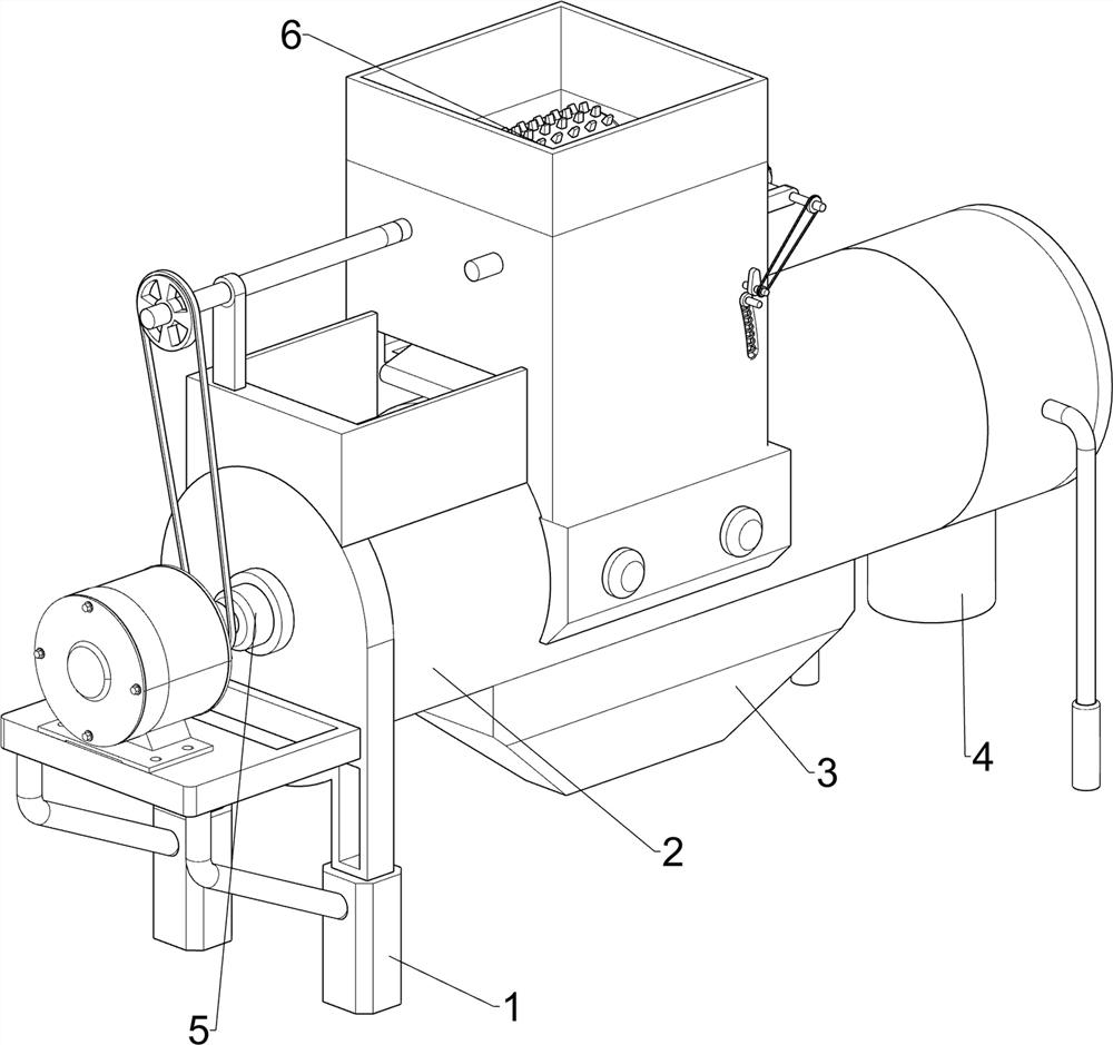
[0024] Such as figure 1 , figure 2 and image 3 As shown, a copper-plastic separation device for cable crushing includes a first bearing seat 1, a cylinder 2, a discharge box 3, a discharge pipe 4, a separation mechanism 5 and a crushing mechanism 6, and the upper side of the first bearing seat 1 is set There is a cylinder 2, a discharge box 3 is provided on the lower side of the middle part of the cylinder 2, a discharge pipe 4 is provided on the lower side of the cylinder 2 away from the first bearing seat 1, and a separation mechanism 5 is provided on the first bearing seat 1. The cylinder 2 is provided with a crushing mechanism 6 .

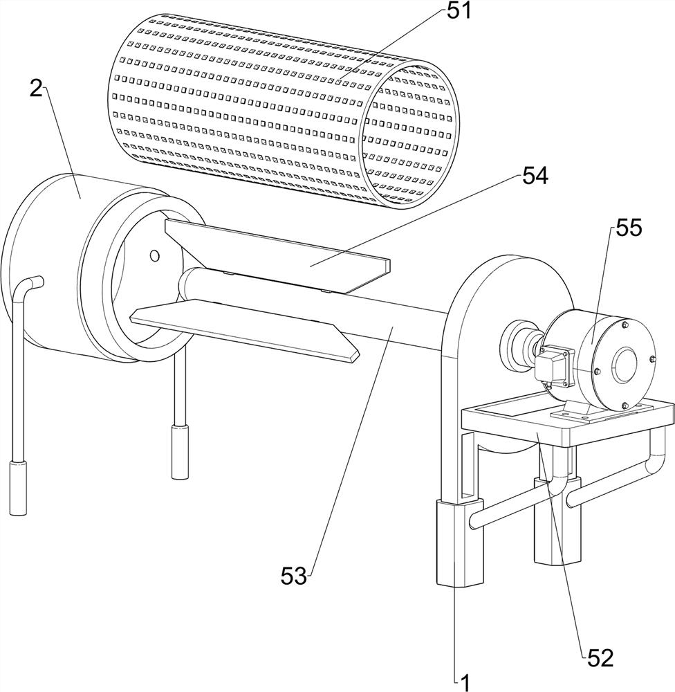
[0025] The separation mechanism 5 includes a circular tube 51, a support plate 52, a first rotating shaft 53, a fan blade 54 and a servo motor 55. The circular tube 51 is arranged in the cylinder 2, and small holes are evenly spaced on the tube wall of the circular tube 51. A support plate 52 is provided on the left side of the first beari...

Embodiment 2

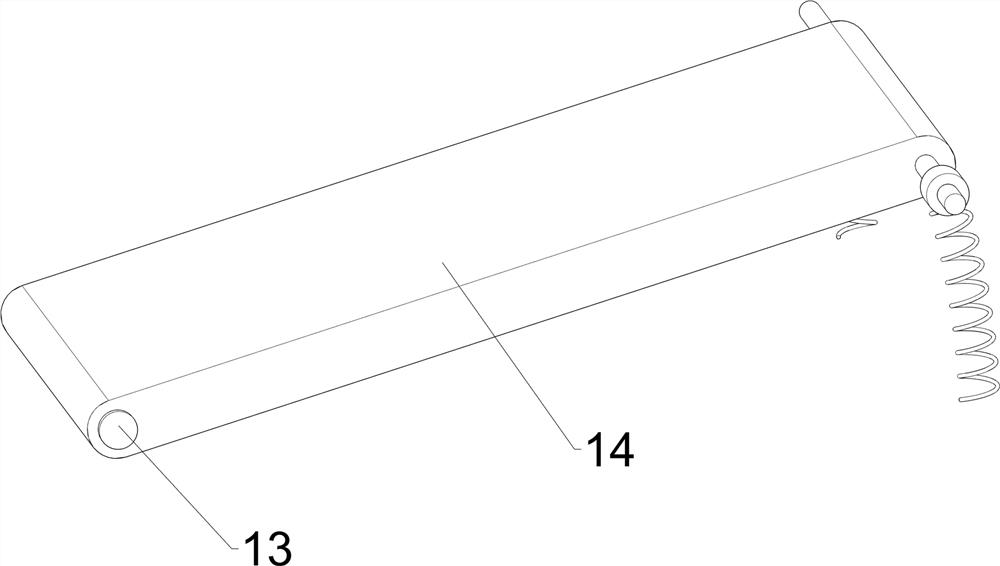
[0029] Such as Figure 4 , with 5 and Figure 6 As shown, on the basis of Embodiment 1, a copper-plastic separation device for cable crushing also includes a third bearing seat 7, a fourth rotating shaft 8, a bevel gear 9, a fifth rotating shaft 10, a cam 11, and a second belt transmission Mechanism 12, the sixth rotating shaft 13, blanking plate 14, slide bar 15 and elastic member 16, the third bearing seat 7 is arranged symmetrically front and back on the right box wall of the blanking box 61, and is provided with between the two third bearing seats 7 The fourth rotating shaft 8, a bevel gear 9 is arranged between the right end of the second rotating shaft 62 on the front side and the adjacent position of the fourth rotating shaft 8, and the two bevel gears 9 mesh with each other, and the right side of the middle part of the box wall on both sides of the front and rear sides of the feeding box 61 is rotated. The fifth rotating shaft 10 is provided with the fifth rotating sh...


PUM


Abstract

The invention relates to a separation device, in particular to a cable crushing copper-plastic separation device. The invention provides a cable breaking copper-plastic separation device which changesa conventional stripping treatment method, realizes efficient separation treatment and can ensure safe operation of workers. The cable breaking copper-plastic separation device comprises a first bearing seat, wherein the upper side of the first bearing seat is provided with a cylinder; a discharging box which is arranged on the lower side of the middle of the cylinder; a discharging pipe which isarranged on the lower side of the side, away from the first bearing seat, of the cylinder; a separation mechanism which is arranged on the first bearing seat; and a crushing mechanism which is arranged on the cylinder. A worker puts a cable needing to be crushed and subjected to copper-plastic separation into the discharging box, the servo motor is started, then the fan blades are driven to rotate around the first rotating shaft to form flowing airflow, meanwhile, the two rollers are driven to oppositely rotate to crush the cable, and the crushed cable is separated in high-speed airflow in the cylinder.

Description

technical field [0001] The invention relates to a separation device, in particular to a cable crushing copper-plastic separation device. Background technique [0002] A cable is a device that transmits electrical energy or signals from one place to another. It is usually a rope-like cable twisted by several or groups of wires. Each group of wires is insulated from each other and often surrounds a cable. The center of the root is twisted, and the entire outer surface is covered with a highly insulating covering layer, which has the characteristics of internal electrification and external insulation. All wires and cables start from conductor processing, and then add insulation, shielding, cabling, sheathing, etc. to the periphery of the conductor to make wire and cable products. [0003] Cables are widely used in many fields such as electric power and machinery. Waste cables refer to those that are burned and damaged by high current and voltage flow, and cannot be used due to...

Claims


Application Information

Patent Timeline
Patent Type & Authority Applications(China)
IPC IPC(8): H01B15/00
CPCH01B15/008Y02W30/82
Inventor 温家深
Owner 安徽省金鸿电线电缆有限公司
Learn More