A stainless steel u-shaped rib butt welding method with drainage function

A welding method, stainless steel technology, applied in welding equipment, manufacturing tools, arc welding equipment, etc., to achieve the effect of easy operation, qualified weld appearance and internal quality, and guaranteed quality

Active Publication Date: 2022-06-24
CHINA RAILWAY SHANQIAO GRP CO LTD +1
View PDF5 Cites 0 Cited by
  • Summary
  • Abstract
  • Description
  • Claims
  • Application Information

AI Technical Summary

Problems solved by technology

[0009] Aiming at the technical problems existing in the U-shaped rib butt welding process of the existing orthotropic bridge deck with the help of stainless steel U-shaped ribs for bridge deck drainage, the invention provides a stainless steel U-shaped rib butt welding method with drainage function

Method used


Image

  • A stainless steel u-shaped rib butt welding method with drainage function
  • A stainless steel u-shaped rib butt welding method with drainage function
  • A stainless steel u-shaped rib butt welding method with drainage function

Examples


Embodiment 1

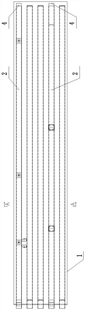
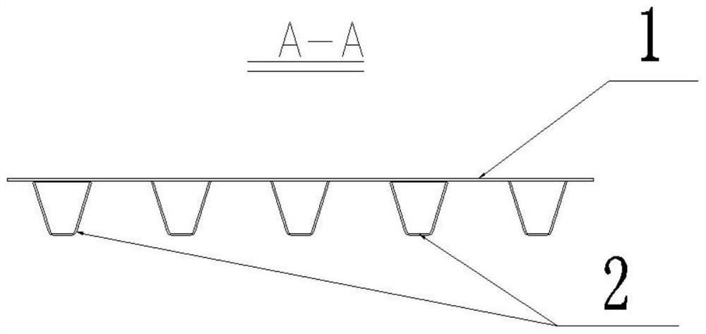
[0038] In order to ensure that the butt welding gap is within the allowable range, a certain length (such as 30cm) of stainless steel sheet inserts 6 is set between the bridge decks 1 of adjacent beam sections, and a certain length (such as 50cm) is set between the stainless steel U-shaped ribs 2. ) of the stainless steel U-rib insert section 5, refer to Figure 4 . The actual length of the stainless steel U-shaped rib embedded section is set according to the actual measurement data after the completion of the on-site beam section assembly and welding, and the principle is to ensure the gap of the butt weld. The machining of the stainless steel U-shaped rib inserting section should be finished by machine tool, and the accuracy of the blunt edge and the size of the opening should be strictly guaranteed, thereby ensuring the welding quality.

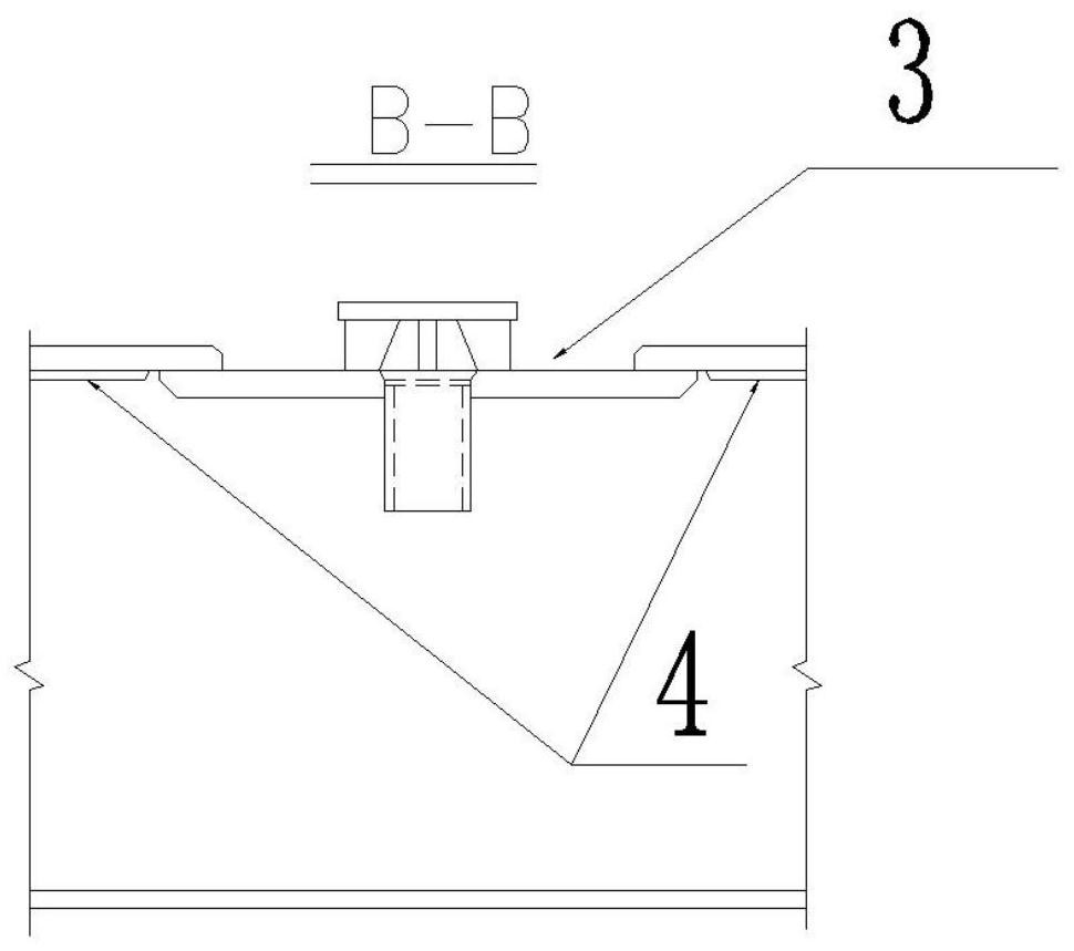
[0039]The back of the weld needs to be filled with inert gas for protection to prevent the weld metal from oxidizing, and the drainage s...

Embodiment 2

[0045] Based on the stainless steel U-rib butt welding method of Example 1, such as Figure 6-7 , including the following steps:

[0046] 1. Assemble and weld the 5mm thick stainless steel sheet insert section, the welding adopts the oxygen gas shielded welding, the overhead welding, the welding material is E309LT1-1 flux-cored wire, the diameter is 1.2mm, the welding current is 160-180A, and the welding voltage is 26-28V , the gas flow is 15-20L / min.

[0047] 2. 100% PT flaw detection shall be carried out 24 hours after the welding of the stainless steel sheet inserting segment. After the flaw detection is qualified, the stainless steel U-shaped rib inserting segment shall be tested and the butt weld groove of the stainless steel U-shaped rib inserting segment shall be inspected. , the groove is required to be a bilateral V-shaped groove, the blunt edge is 0mm, the groove angle is 60±5°, and the gap is 3-5mm. Figure 8 , if it does not meet the requirements, it will be repa...


PUM

PropertyMeasurementUnit
diameteraaaaaaaaaa

Abstract

The invention provides a stainless steel U-shaped rib butt welding method with drainage function. A certain length of stainless steel thin plate embedded section is set between the bridge decks of adjacent beam sections, and a certain length of stainless steel U-shaped rib is set between the stainless steel U-shaped ribs. Shaped rib embedding section; the side of the stainless steel U-shaped rib close to the butt weld is pasted with water-soluble paper through water sol, the butt weld is sealed with tape paper, and an air vent is set on the top tape paper, stainless steel U-shaped rib, bridge deck 1. The water-soluble paper on both sides of the butt weld and the stainless steel U-shaped rib embedding section together form a partially enclosed space; the side of the stainless steel U-shaped rib embedding section is provided with an air-filling hole for filling protective gas. The present invention uses water-soluble paper to artificially manufacture a closed space around the butt weld to solve the problem that the shielding gas is inconvenient to fill, and realizes filling the welding shielding gas in a narrow, long and obstructed space inside.

Description

technical field [0001] The invention relates to the technical field of U-shaped rib butt welding, in particular to a stainless steel U-shaped rib butt welding method with drainage function. Background technique [0002] The orthotropic steel bridge deck is one of the important components of the steel structure bridge, which usually consists of the bridge deck and its bottom U-shaped rib. The top of the deck is a concrete deck, and the bottom U-shaped rib acts to increase stiffness and fatigue resistance. With the continuous innovation and improvement of bridge technology, in some bridge structures, in order to increase the drainage function of the bridge deck on the basis of the original bridge deck, the material of some U-shaped ribs is replaced from carbon steel to stainless steel. The bottom surface of the carbon steel bridge deck is provided with a layer of stainless steel sheet, which forms a corrosion-resistant drainage space with the stainless steel U-shaped rib, so ...

Claims


Application Information

Patent Timeline
Patent Type & Authority Patents(China)
IPC IPC(8): B23K9/16B23K9/167B23K9/235B23K33/00B23K9/025
CPCB23K9/16B23K9/167B23K9/235B23K33/004B23K9/025B23K9/0026
Inventor 刘振刚刘万里王杰于洋常国光李久成尤元霞马春江
Owner CHINA RAILWAY SHANQIAO GRP CO LTD
Why Eureka
Try Eureka