Electric welding machine capable of automatically replacing welding electrodes

A technology of automatic replacement and welding electrodes, applied in welding accessories, grinding drive devices, grinding machine parts, etc., can solve the problems of operator sucking, affecting welding effect, unable to weld welds, etc., to accelerate the passage of current , The effect of shortening clamping time and improving work efficiency

Inactive Publication Date: 2021-01-29
温州新兰智能科技有限公司
View PDF0 Cites 4 Cited by
  • Summary
  • Abstract
  • Description
  • Claims
  • Application Information

AI Technical Summary

Problems solved by technology

[0002] In our daily life, we often use welding rods for metal gap welding. Welding rods need to be used in conjunction with electric welding machines. Traditional electric welding machines do not have the function of automatically clamping welding rods. At the same time, a large amount of toxic gases will be generated during the welding process. It is easy to cause the operator to inhale, which will affect the physical and mental health of the operator. When welding, it is often encountered in a narrow and dark space, which will affect the operator's sight, and the welding seam cannot be welded well, which will affect Welding effect, a kind of electric welding machine that can automatically change welding rod described in the present invention can solve the above problems

Method used


Image

  • Electric welding machine capable of automatically replacing welding electrodes
  • Electric welding machine capable of automatically replacing welding electrodes
  • Electric welding machine capable of automatically replacing welding electrodes

Examples


Embodiment Construction

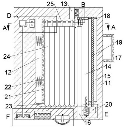
[0021] Combine below Figure 1-8 The present invention is described in detail, wherein, for the convenience of description, the orientations mentioned below are defined as follows: figure 1 The up, down, left, right, front and back directions of the projection relationship itself are the same.

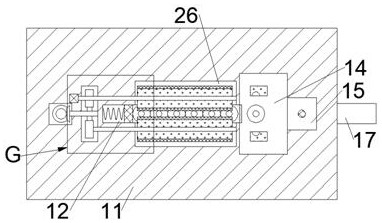
[0022] An electric welding machine capable of automatically replacing welding rods according to the present invention includes a body 11, a storage chamber 12 is provided inside the body 11, and the upper wall surface on the right side of the storage chamber 12 communicates with the upper end surface of the body 11 A feed hole 13 is provided, the right wall of the feed hole 13 is communicated with a clamping cavity 14 extending to the right, the right wall of the clamping cavity 14 is connected with a lift cavity 15 extending to the right, and the storage cavity 12 The lower wall is communicated with a guide chute 23 with an upward opening, and a feeding plate 21 capable of sliding le...


PUM


Abstract

The invention discloses an electric welding machine capable of automatically replacing welding electrodes. The machine comprises a machine body, a storage cavity is formed in the machine body, a feeding hole is formed between the upper wall face of the right side of the storage cavity and the upper end face of the machine body in a communicating manner, and a clamping cavity extending rightwards is formed in the right wall face of the feeding hole in a communicating manner. A lifting cavity extending rightwards is arranged in the right wall face of the clamping cavity in a communication manner, and a guide sliding groove with an upward opening is formed in the lower wall face of the storage cavity in a communication manner. According to the electric welding machine, the welding electrodesare stored in the electric welding machine, so that the welding electrodes can be clamped in time, the clamping time is effectively shortened, the working efficiency is improved, meanwhile, the clamping position of the upper end of a core wire can be polished, impurities on the surface of the core wire can be effectively removed, passing of current is accelerated, coating combustion can be more sufficient, meanwhile, toxic gas generated during electric welding can be recycled through the machine, and the situation that operators inhale the toxic gas, and physical and psychological health is affected is avoided.

Description

technical field [0001] The invention relates to the field of welding electrodes, in particular to an electric welding machine capable of automatically replacing welding electrodes. Background technique [0002] In our daily life, we often use welding rods for metal gap welding. Welding rods need to be used in conjunction with electric welding machines. Traditional electric welding machines do not have the function of automatically clamping welding rods. At the same time, a large amount of toxic gases will be generated during the welding process. It is easy to cause the operator to inhale, which will affect the physical and mental health of the operator. When welding, it is often encountered in a narrow and dark space, which will affect the operator's sight, and the welding seam cannot be welded well, which will affect Welding effect, a kind of electric welding machine that can automatically replace welding rod described in the present invention, can solve the above-mentioned...

Claims


Application Information

Patent Timeline
Patent Type & Authority Applications(China)
IPC IPC(8): B23K9/32B24B27/00B24B27/033B24B47/12B24B55/12
CPCB23K9/32B24B27/0076B24B27/033B24B47/12B24B55/12
Inventor 张重亚
Owner 温州新兰智能科技有限公司
Why Eureka
Try Eureka