
A transmission mechanism of a two-stage flapping-wing aircraft

A technology of transmission mechanism and flapping wing aircraft, which is applied in the field of flapping wing mechanism, can solve the problems of limiting the limit output power of the mechanism, increasing the rigidity of the rotating shaft, and the phase asynchrony of the left and right wings, so as to achieve simple stress and increase output power , the effect of small deformation

Active Publication Date: 2022-06-24
ZHEJIANG UNIV
View PDF7 Cites 0 Cited by
  • Summary
  • Abstract
  • Description
  • Claims
  • Application Information

AI Technical Summary

Problems solved by technology

However, the use of cantilever support will make the gear fixing unreliable. During the flight, due to the impact load, the rigidity of the rotating shaft is very high. If the shaft rigidity is too small, it is easy for the two driven gears to slip, which makes the phase of the left and right wings out of sync; Due to insufficient gear meshing capacity and small bearing capacity, the ultimate output power of the mechanism is limited
The crank and the driven gear in the gear set are fixed, and the force on the gear is more complicated. At the same time, the crank has a certain deformation, which makes the actual flutter action deviate from the theoretical flutter, and intensifies the requirement for the stiffness of the shaft.

Method used


Image

  • A transmission mechanism of a two-stage flapping-wing aircraft
  • A transmission mechanism of a two-stage flapping-wing aircraft
  • A transmission mechanism of a two-stage flapping-wing aircraft

Examples


Embodiment Construction

[0033] In order to understand the above objects, features and advantages of the present invention more clearly, the present invention will be further described in detail below with reference to the accompanying drawings and specific embodiments. It should be noted that the embodiments of the present invention and the features in the embodiments may be combined with each other under the condition of no conflict.

[0034] Many specific details are set forth in the following description to facilitate a full understanding of the present invention. However, the present invention can also be implemented in other ways different from those described herein. Therefore, the protection scope of the present invention is not limited by the specific details disclosed below. Example limitations.

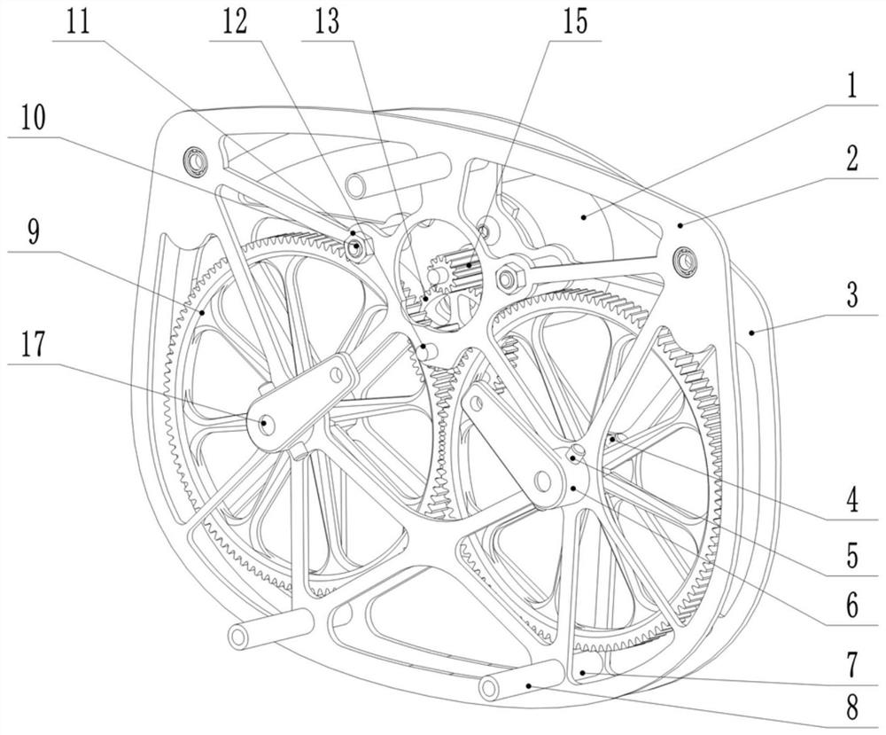
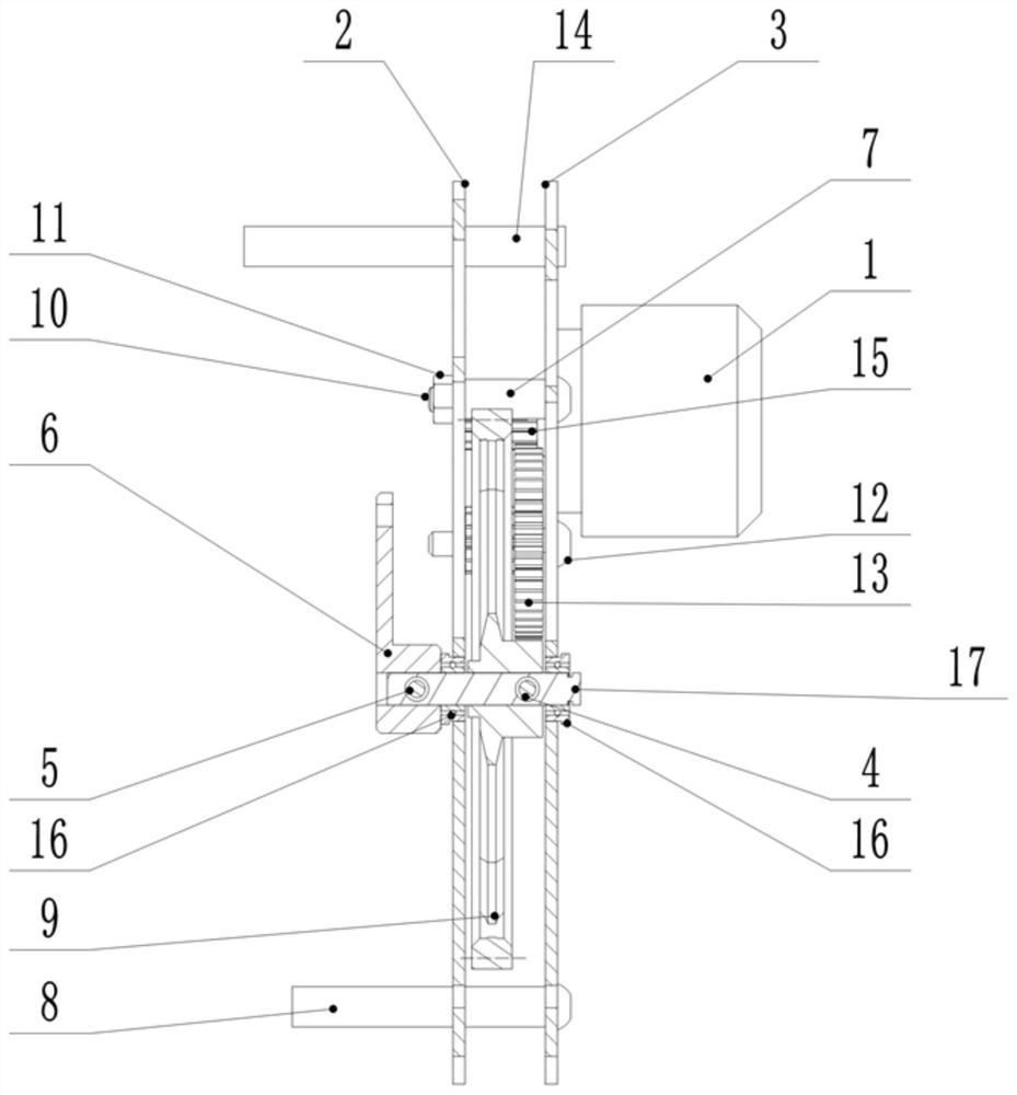
[0035] A two-stage flapper transmission mechanism, comprising a motor 1, a frame middle plate 2, a frame rear plate 3, a pair of gear pins 4, a pair of crank pins 5, a pair of cranks 6, and four fi...


PUM


Abstract

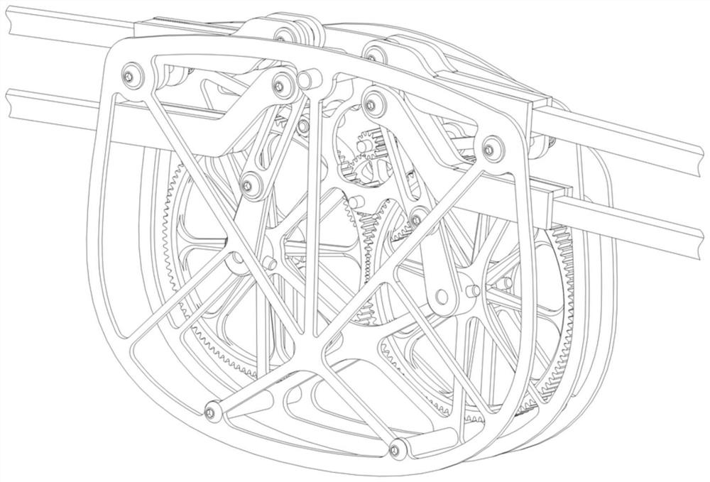
The invention discloses a transmission mechanism of a two-stage flapping wing aircraft, which comprises a motor, a frame middle plate, a frame rear plate, a pair of cranks, a pair of final gears, a secondary gear shaft, a secondary double gear, and a primary gear. , a pair of final drive shafts. In the transmission mechanism of the double-stage flapping wing aircraft of the present invention, the final gear and the crank of the flapping mechanism are respectively fixed to the final transmission shaft through bolts, and both ends of the final gear are supported, so that the two final gears are easily and easily stressed. reliable. The invention solves the problem that the final gear is supported by a traditional cantilever, which is easy to slip and has low limit power; compared with the common fixed connection between the final gear and the crank of the flutter mechanism, the final gear is separated from the crank of the flutter mechanism , the stress on the final gear and the crank is relatively simple, which makes the deformation of the crank smaller, and the flapping action is less affected by the elastic deformation of the material, making the flapping action closer to the theoretical design state.

Description

technical field [0001] The invention relates to a flapping mechanism, in particular to a two-stage flapper transmission mechanism. Background technique [0002] The dual-segment flapping-wing aircraft is a further bionic flying robot. It has the characteristics of high flight efficiency, low noise, strong bionic shape, and good flexibility. It is widely used in military, civil and other technological fields. All have broad prospects for development. [0003] In nature, the flight movements of birds that fly long distances can be divided into four stages: down, folded, up, and flat, and flapping in this cycle. During the flapping process, the wings are swayed up and down, and the wings are folded before the upper flap, which can effectively reduce the resistance of the upper flap and reduce the energy consumption; [0004] Although the double-segment flapping wing has the advantage of reducing energy consumption and improving energy utilization during the up-flying process,...

Claims


Application Information

Patent Timeline
Patent Type & Authority Patents(China)
IPC IPC(8): B64C33/02
CPCB64C33/02
Inventor 杜昌平杨睿郑耀宋广华叶志贤陈俊胤韩建福张泽坤王思鹏
Owner ZHEJIANG UNIV
Learn More