Pressing and rotating mechanism for gasket in cosmetic bottle body

A technology of pressing and rotating, inner gasket, applied in the directions of bottle/container caps, closures, household utensils, etc. The effect of feeding and feeding, improving the pressing efficiency

Inactive Publication Date: 2021-01-29
温州巢语化妆品有限公司
View PDF7 Cites 0 Cited by
  • Summary
  • Abstract
  • Description
  • Claims
  • Application Information

AI Technical Summary

Problems solved by technology

[0003] However, when the gasket of the current cosmetic bottle body is compressed, it will be compressed by the expansion and contraction of the cylinder. This compression method will produce a short interruption in the middle, and the compression cannot be performed continuously, resulting in too slow compression efficiency. And when the cylinder is being compressed, air cannot be blown into the bottle, and dust in the flat body cannot be removed.

Method used


Image

  • Pressing and rotating mechanism for gasket in cosmetic bottle body
  • Pressing and rotating mechanism for gasket in cosmetic bottle body
  • Pressing and rotating mechanism for gasket in cosmetic bottle body

Examples


Embodiment 1

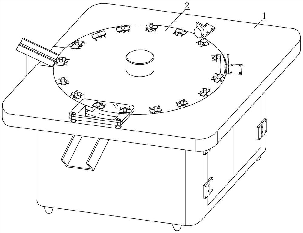
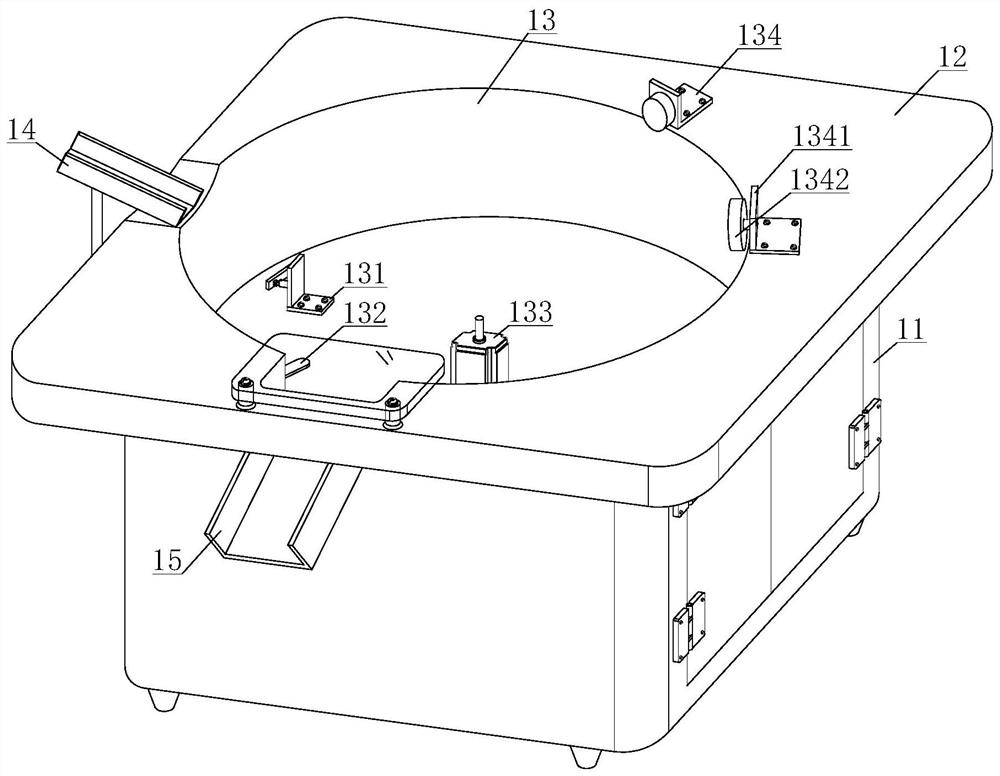
[0034] see Figure 1-2, a gasket pressing and rotating mechanism in a cosmetic bottle, including a pressing device 1 and a rotating device 2, the upper end of the pressing device 1 is equipped with a rotating device 2, and the pressing device 1 includes a main machine 11, a rotating table 12, and a rotating groove 13 , the rotary slot 13 includes a first connecting piece 131, a blanking plate 132, a servo motor 133 and a second connecting piece 134, the second connecting piece 134 includes a second support plate 1341 and a roller 1342, and one end of the second connecting piece 134 is installed sideways There is a second support plate 1341, a roller 1342 is installed on the side of one end of the second support plate 1341, a first connecting piece 131 is installed on the bottom surface of the inner cavity of the rotating groove 13, and a blanking plate 132 is installed on the inner cavity wall of the rotating groove 13, and The blanking plate 132 is positioned at one end side ...

Embodiment 2

[0040] see Figure 1-2 , a gasket pressing and rotating mechanism in a cosmetic bottle, including a pressing device 1 and a rotating device 2, the upper end of the pressing device 1 is equipped with a rotating device 2, and the pressing device 1 includes a main machine 11, a rotating table 12, and a rotating groove 13 , the rotary slot 13 includes a first connecting piece 131, a blanking plate 132, a servo motor 133 and a second connecting piece 134, the second connecting piece 134 includes a second support plate 1341 and a roller 1342, and one end of the second connecting piece 134 is installed sideways There is a second support plate 1341, a roller 1342 is installed on the side of one end of the second support plate 1341, a first connecting piece 131 is installed on the bottom surface of the inner cavity of the rotating groove 13, and a blanking plate 132 is installed on the inner cavity wall of the rotating groove 13, and The blanking plate 132 is positioned at one end side...


PUM


Abstract

The invention discloses a pressing and rotating mechanism for a gasket in a cosmetic bottle body. The pressing and rotating mechanism comprises a pressing device and a rotating device, wherein the rotating device is arranged at the upper end of the pressing device; when the cosmetic bottle body falls into a material groove along a feeding groove, a servo motor rotates to drive a rotating disc to rotate at a constant speed; when a material rotates to the lower end of a roller, a pressing rod is pressed down by the roller, so that the pressing rod can move downwards; the pressing rod moves to enable a lower pressing head to descend, and the lower pressing head descends to enable the gasket in the bottle body to be pressed; through the cooperation of the rotating disc and the pressing device,the non-stop pressing is achieved; compared with a traditional intermittent pressing mode through an air cylinder, the mode is faster, so that the pressing efficiency is improved; and a fourth springis wound on the outer surface of the lower pressing head, and under the elastic resilience of the fourth spring, the lower pressing head can automatically rebound after the pressing is finished, so that discharging and feeding are facilitated.

Description

technical field [0001] The invention relates to the technical field of compression devices, in particular to a gasket compression rotation mechanism in a cosmetic bottle. Background technique [0002] Cosmetics refers to spread on any part of the human body surface by smearing, spraying or other similar methods, and the cosmetics are filled through the cosmetic bottle body. When filling and sealing, gaskets are used for sealing. Through the cosmetic bottle body The upper lid is rotated and sealed to prevent cosmetics from leaking out after use. [0003] However, when the gasket of the current cosmetic bottle body is compressed, it will be compressed by the expansion and contraction of the cylinder. This compression method will produce a short interruption in the middle, and the compression cannot be performed continuously, resulting in too slow compression efficiency. And the cylinder cannot blow air in the bottle body when compressing, and the dust in the flat body cannot ...

Claims


Application Information

Patent Timeline
IPC IPC(8): B67B6/00
CPCB67B6/00
Inventor 黄纯彦
Owner 温州巢语化妆品有限公司
Why Eureka
Try Eureka