
A double-stage reinforced soil abutment with densely arranged reinforcements and its construction method

A technology of reinforced soil and abutments, applied in the direction of bridges, artificial islands, bridge construction, etc., can solve the problems of large distance between the pedestal and the wall, increased land cost, limited bearing capacity, etc., to achieve low cost, save construction site, The effect of improving the carrying capacity

Active Publication Date: 2022-03-01
WUHAN UNIV
View PDF19 Cites 0 Cited by
  • Summary
  • Abstract
  • Description
  • Claims
  • Application Information

AI Technical Summary

Problems solved by technology

However, the current reinforced soil abutments are difficult to balance in terms of stability and construction convenience. For example, Chinese patent document CN202881845U discloses a flexible reinforced soil abutment for highway bridges, which can only be used in projects with low heights. To ensure that it has sufficient bearing capacity, if the distance between the pedestal and the wall is too large, too much space will be wasted in practice; Chinese patent document CN204676593U discloses a super-high integral steel-plastic grid reinforced earth abutment retaining wall structure, Although it can be used in higher projects, its bearing capacity is relatively limited, and a lot of space is wasted, which indirectly increases the cost of land. In addition, its structure is too complicated and the construction is difficult

Method used


Image

  • A double-stage reinforced soil abutment with densely arranged reinforcements and its construction method
  • A double-stage reinforced soil abutment with densely arranged reinforcements and its construction method
  • A double-stage reinforced soil abutment with densely arranged reinforcements and its construction method

Examples


Embodiment

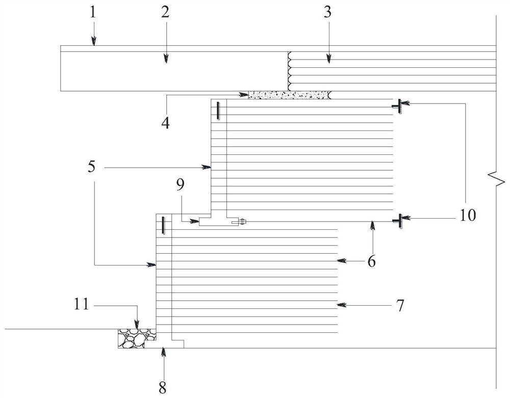
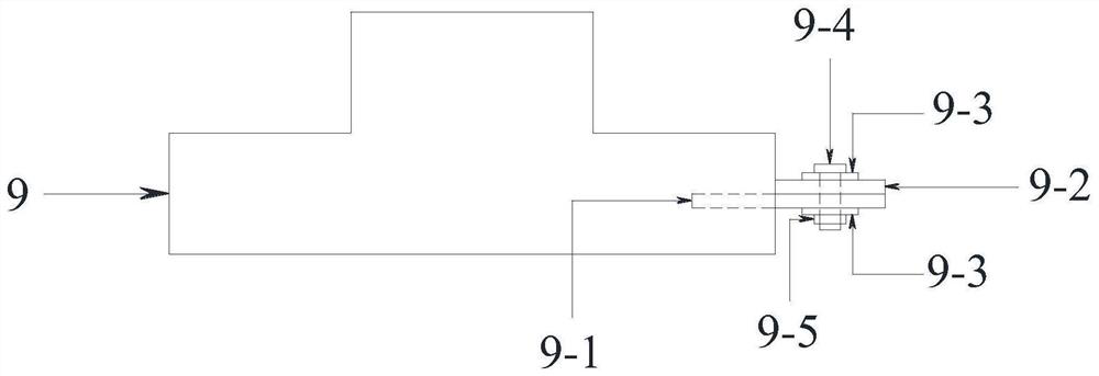
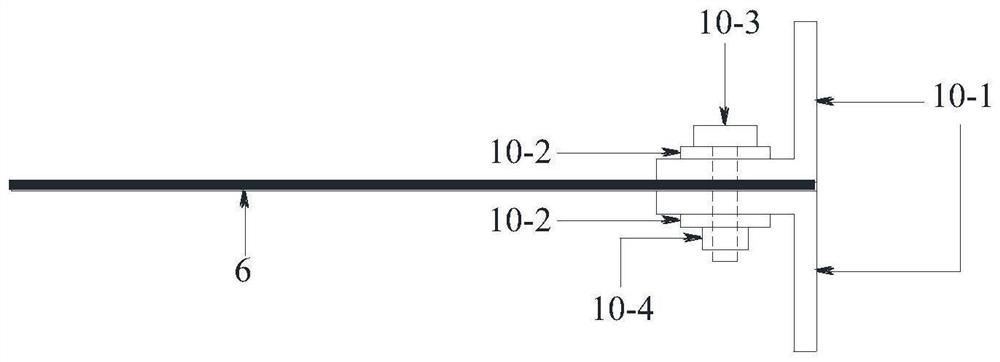
[0038] Such as figure 1 A two-stage reinforced soil abutment with closely arranged reinforcement materials is shown, mainly including pavement structure 1, bridge superstructure 2, closely spaced reinforced soil approach road 3, pedestal 4, upper reinforced soil Abutment system, lower reinforced soil abutment system and gravel protection body 11.

[0039] The pedestal 4 is a reinforced concrete slab structure, which directly supports the bridge superstructure 2 and the closely spaced reinforced soil approaches 3, and evenly distributes the loads of the bridge superstructure 2 and the closely spaced reinforced soil approaches 3 on the upper reinforced soil abutment The top of the bridge is conducive to keeping the bridge superstructure 2 and the closely spaced reinforced soil approach road 3 smooth. Close-spaced reinforced soil approach road 3 adopts a back-wrapped reinforced soil structure with a spacing of 0.2m. This type of reinforced soil approach road has relatively high ...


PUM


Abstract

The invention discloses a double-stage reinforced soil abutment with closely arranged reinforcement materials, comprising a road-bridge connection support system, an upper-level reinforced soil abutment system and a lower-level reinforced soil abutment system, and the road-bridge connection support system includes a road surface structure , bridge superstructure, closely spaced reinforced soil approaches and pedestals, the pavement structure is located on top of the bridge superstructure and closely spaced reinforced soil approaches, and the bridge superstructure and closely spaced reinforced soil approaches are arranged in parallel; the superior The reinforced soil abutment system is set on the upper part of the lower reinforced soil abutment system, and the reinforcements inside both are closely arranged. The invention also provides a construction method of the double-stage reinforced abutment. The beneficial effects of the present invention are: the tight arrangement of reinforcements can effectively increase its bearing capacity, the improvement of the previous single-stage abutment into a double-stage abutment can effectively reduce the overturning moment, improve the external stability of the structure, and the use of anchoring devices can effectively Improve stability, reduce deformation during service, and lay the foundation for the expansion of its application range.

Description

technical field [0001] The invention relates to the technical field of highway bridge construction, in particular to a double-stage reinforced soil abutment with closely arranged reinforcement materials and a construction method thereof. Background technique [0002] Reinforced earth abutments are widely used in transportation infrastructure. However, the current reinforced soil abutments are difficult to balance in terms of stability and construction convenience. For example, Chinese patent document CN202881845U discloses a flexible reinforced soil abutment for highway bridges, which can only be used in projects with low heights. To ensure that it has sufficient bearing capacity, if the distance between the pedestal and the wall is too large, too much space will be wasted in practice; Chinese patent document CN204676593U discloses a super-high integral steel-plastic grid reinforced earth abutment retaining wall structure, Although it can be used in higher projects, its bea...

Claims


Application Information

Patent Timeline
Patent Type & Authority Patents(China)
IPC IPC(8): E02D29/02E01D19/02E01D21/00E01D19/00
CPCE01D19/02E01D21/00E01D19/00
Inventor 郑烨炜郭文灏张军李福秀
Owner WUHAN UNIV
Learn More