Air film cooling hole pattern structure

A technology of air film cooling and air film holes, which is applied to the supporting elements of blades, engine elements, machines/engines, etc., can solve the problems that the cold air film is not fully spread and the air film cooling efficiency is not well improved, etc. Achieve good practical application value, improve film cooling efficiency, and improve the effect of cooling capacity

Active Publication Date: 2021-01-29
SHANGHAI JIAO TONG UNIV
View PDF11 Cites 7 Cited by
  • Summary
  • Abstract
  • Description
  • Claims
  • Application Information

AI Technical Summary

Problems solved by technology

In actual use, the middle flow area of ​​the expansion channel is the largest, while the flow area on both sides gradually decreases, so the cold air film has not been fully spread in the span direction, resulting in a poor improvement in air film cooling efficiency

Method used


Image

  • Air film cooling hole pattern structure
  • Air film cooling hole pattern structure
  • Air film cooling hole pattern structure

Examples


Embodiment Construction

[0025] The present invention will be described in detail below in conjunction with the accompanying drawings and specific embodiments. This embodiment is carried out on the premise of the technical solution of the present invention, and detailed implementation and specific operation process are given, but the protection scope of the present invention is not limited to the following embodiments.

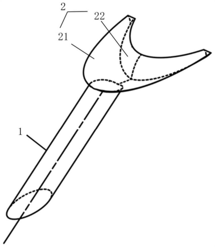
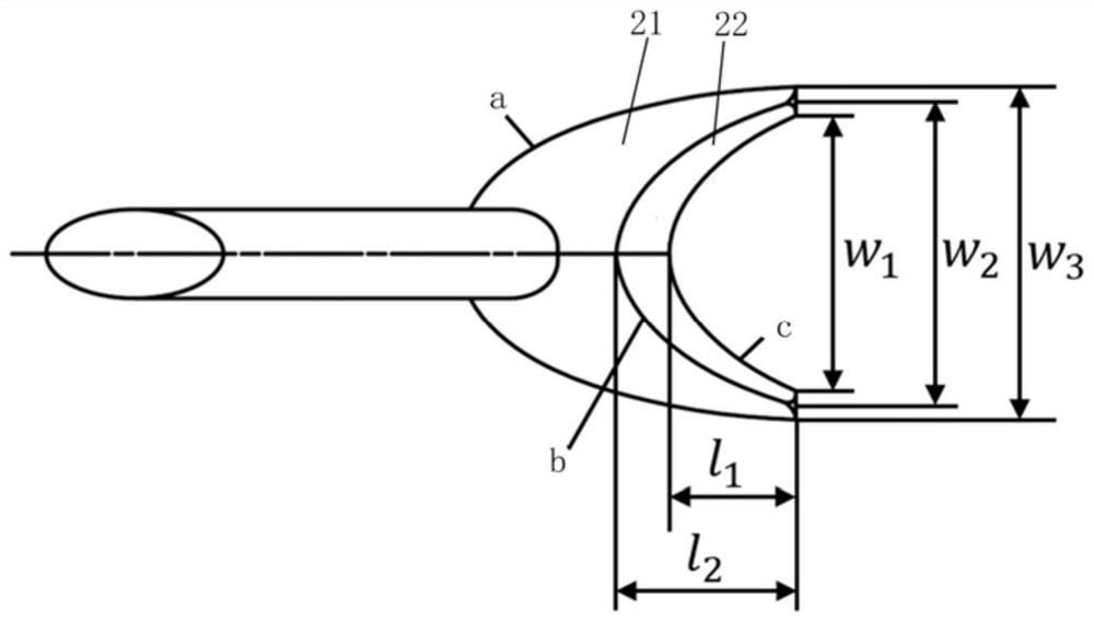
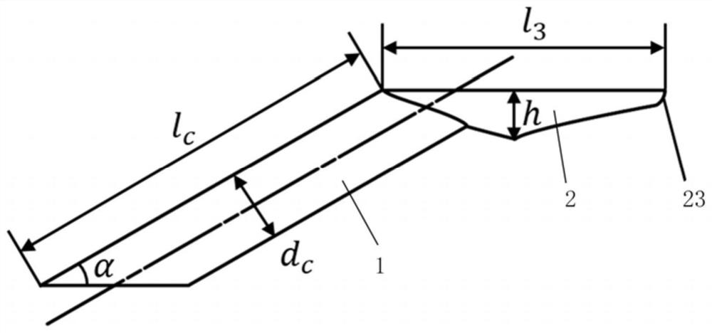
[0026] Such as Figure 1~3 As shown, this embodiment provides a film cooling hole structure. The structure includes a film hole and a wall, and the outlet of the film hole is located in the upstream area of ​​the wall. The air film hole includes a cylindrical section 1 and an expansion section 2 , one end of the cylindrical section 1 is a cold air inlet, and the other end of the cylindrical section 1 is connected to the expansion section 2 . The opening on the top surface of the expansion section 2 is the outlet of the gas film hole on the wall;

[0027] Cylindrical diameter d of c...


PUM


Abstract

The invention relates to an air film cooling hole pattern structure which comprises an air film hole and a wall face, wherein an outlet of the air film hole is located in the upstream area of the wallface, the air film hole comprises a cylindrical section and an expansion section, one end of the cylindrical section is a cold air inlet, the other end of the cylindrical section is connected with the expansion section, and an opening is formed in the top face of the expansion section, namely the outlet of the air film hole. The bottom surface of the expansion section is a crescent concave curvedsurface with a sharp corner end, and the crescent concave curved surface is communicated with the cylindrical section. Compared with the prior art, the air film cooling hole pattern structure has thebeneficial effects that on one hand, due to the coanda effect, cold air can expand towards the two sides after reaching the position of the crescent concave curved surface expansion outlet with the sharp corner end, and the transverse spreading area of the cold air film is increased; and on the other hand, the expansion type outlet can effectively reduce the momentum of cold air jet flow, cold air can be well attached to the wall face, and therefore the air film cooling efficiency is improved.

Description

technical field [0001] The invention relates to the technical field of film cooling of turbine blades, in particular to a film cooling hole structure. Background technique [0002] In order to further improve the working efficiency of gas turbines and aeroengines, an effective method is to continuously increase the temperature of the turbine inlet. The turbine inlet temperature of modern gas turbines and aero-engines is already far higher than the tolerance temperature of the turbine blade material, so various cooling measures must be used to reduce the temperature of the turbine blade itself. Air film cooling is one of the main ways of cooling turbine blades at present. Its basic principle is to extract a part of high-pressure cold air from the compressor, transport it to the internal channel of the turbine blade, and then spray it out from the air film cooling holes on the blade. A thin film of cold air is formed to protect the blades from being ablated by high temperatur...

Claims


Application Information

Patent Timeline
Patent Type & Authority Applications(China)
IPC IPC(8): F01D5/18
CPCF01D5/186F05D2260/2214
Inventor 周文武张栩彭迪刘应征邵弘毅
Owner SHANGHAI JIAO TONG UNIV
Why Eureka
Try Eureka