Heat dissipation assembly for electronic product production and using method thereof

A technology for electronic products and heat-dissipating components, applied in the field of heat-dissipating components used in the production of electronic products, can solve the problems of deformation of electronic products, low cooling efficiency, easy occurrence of airflow, etc., and achieve the effect of increasing specific heat capacity, reducing time, and improving the rate of dissipation

Active Publication Date: 2021-01-29
南通川本橡塑制品有限公司
View PDF20 Cites 0 Cited by
  • Summary
  • Abstract
  • Description
  • Claims
  • Application Information

AI Technical Summary

Problems solved by technology

[0003] The purpose of the present invention is to provide a heat dissipation component for the production of electronic products and its use method, so as to solve the problem that the existing air-cooled equipment proposed in the above-mentioned background technology has low cooling efficiency for electronic products, and air flow easily causes deformation of electronic products The problem

Method used


Image

  • Heat dissipation assembly for electronic product production and using method thereof
  • Heat dissipation assembly for electronic product production and using method thereof
  • Heat dissipation assembly for electronic product production and using method thereof

Examples


Embodiment 1

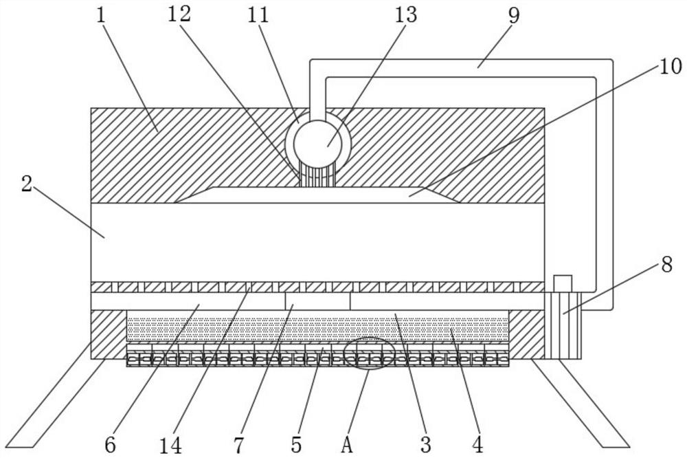
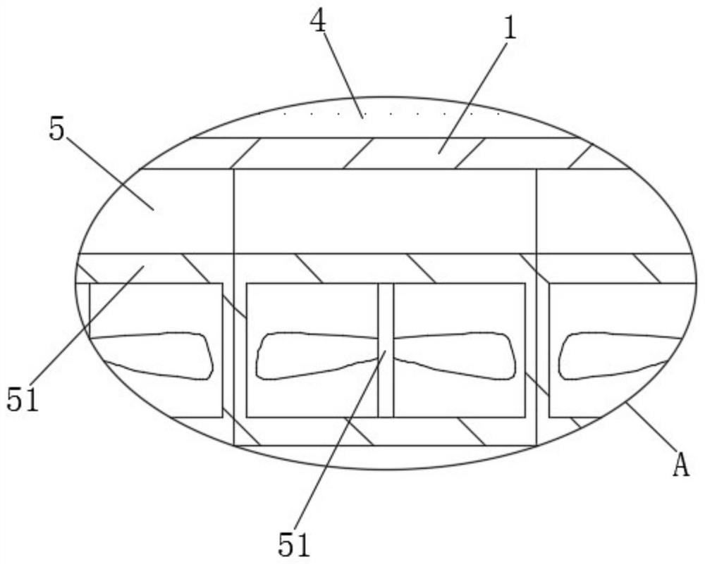
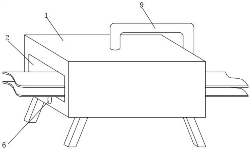
[0027] see Figure 1-4 , the present embodiment provides a heat dissipation assembly for the production of electronic products and its use method, including a fixed table 1, the inside of the fixed table 1 is provided with a transmission chamber 2 along the horizontal direction, and the interior of the fixed table 1 is directly above the transmission chamber 2 An air duct 10 is provided, and a water tank 3 is provided on the inside of the fixed platform 1 near the center and directly below the transmission chamber 2 , and the inside of the water tank 3 is filled with a coolant 4 .

[0028] The air bag 13 is connected directly above the air channel 10 through the air duct 12, the air bag 13 is connected to the air pump 8 through the air channel 9, and the suction end of the air pump 8 is connected to the air chamber 6 arranged directly above the water tank 3, and the air pump 8 and the air chamber 6 utilize a siphon The principle is to extract the coolant 4 inside the water tan...

Embodiment 2

[0041] see figure 1 , made further improvement on the basis of Embodiment 1: the buffer chamber 11 is a hollow spherical structure, the inside of the buffer chamber 11 is equipped with an airbag 13, the outer wall of the top side of the airbag 13 is connected with the end of the airway 9, and the bottom of the airbag 13 The outer wall of the side is connected with the top of the air duct 12. There are multiple air ducts 12 arranged in an array on the inner wall of the top side of the air duct 10. The air bag 13 can expand when the air pump 8 is running, and pass through Its own deformation can ensure a more uniform airflow. When the air pump 8 stops running, the inflated airbag 13 can use its own elastic potential energy to accelerate the airflow to a certain extent and slow down the rate of airflow change, thereby preventing electronic products from being subjected to strong airflow. The influence of unevenness appears.


PUM


Abstract

The invention discloses a heat dissipation assembly for electronic product production and a using method thereof. The heat dissipation assembly comprises a fixing table, a conveying cavity is formed in the fixing table in the horizontal direction, and a water tank is formed in the position close to the center of the interior of the fixing table and located under the conveying cavity; the water tank is filled with a coolant, and a thermoelectric refrigeration sheet is fixed under the outer wall of the bottom side of the water tank; an air cavity is formed in the position, located over the watertank, of the interior of the fixing table, air holes are formed in the four side faces of the air cavity and located in the outer wall of the fixing table, and an air pump is fixed to the side face of one of the air holes; an air channel communicating with the air hole is fixed to the outer wall of the fixing table, and the end, away from the air holes, of the air channel extends to the top faceof the fixing table; and an air duct is formed in the position, over the conveying cavity, in the fixing table, and a buffer cavity communicates with the air duct through an air pipe. Through cooperative use of all the devices, the cooling efficiency of the air cooling equipment on electronic products can be improved, airflow is prevented from directly acting on the electronic products, and the situation that the electronic products deform is prevented.

Description

technical field [0001] The invention relates to the technical field of heat dissipation components for production of electronic products, in particular to a heat dissipation component for production of electronic products and a method for using the same. Background technique [0002] After the electronic product is formed, cooling it quickly can prevent the electronic product from being deformed due to pressure during the later processing, and will not cause damage to the production equipment. However, the cooling method of the existing cooling equipment is mostly wind. cold, but the cooling efficiency of air-cooled equipment on electronic products is low, and the airflow generated by air-cooled equipment directly acts on the surface of electronic products, and the airflow has a greater impact on electronic products. For newly formed electronic products, It is easy to cause deformation of electronic products, which in turn affects the yield rate of electronic products. Con...

Claims


Application Information

Patent Timeline
Patent Type & Authority Applications(China)
IPC IPC(8): F25D15/00F25D17/08F25D25/04F25B21/02
CPCF25D15/00F25D17/08F25D25/04F25B21/02
Inventor 张强
Owner 南通川本橡塑制品有限公司
Why Eureka
Try Eureka