
3D electromagnetic scanning system

A scanning system, 3D technology, applied in the direction of electromagnetic field characteristics, measuring electrical variables, measuring devices, etc., can solve problems such as inability to express the spatial position relationship of test points, high operation requirements, and difficult probe identification

Active Publication Date: 2021-01-29
BEIJING INST OF SPACECRAFT SYST ENG
View PDF9 Cites 1 Cited by
  • Summary
  • Abstract
  • Description
  • Claims
  • Application Information

AI Technical Summary

Problems solved by technology

[0007] During the testing process of this method, two cameras need to be fixed at a fixed position to continuously shoot. During the testing process, it is necessary to avoid the blocking of the camera by the operation action, and the operation requirements are high. Secondly, the image recognition of the probe position is suitable for special configuration probes and probes with small color differences from the measured object. Recognition is difficult; in addition, the information of the measured object is displayed in a flat image, which cannot express the three-dimensional information such as the protrusions and depressions of the measured object, and cannot express the spatial position relationship between the test point and the surface of the measured object
[0008] It can be seen that in the prior art, the existing technical solutions for spatial three-dimensional electromagnetic scanning still have deficiencies in terms of ease of operation and visual display of results

Method used


Image

  • 3D electromagnetic scanning system
  • 3D electromagnetic scanning system
  • 3D electromagnetic scanning system

Examples


example 3

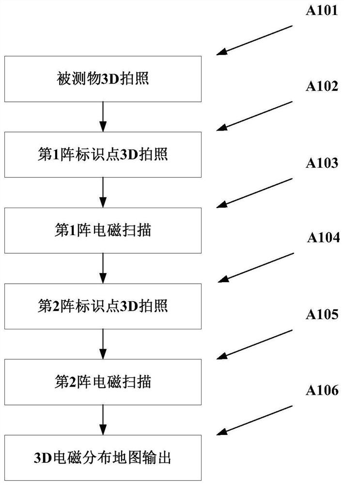
[0047] In this example, the measured object is a 4m wide × 2m high object, and a 2.2GHz radiation source sample is placed in the measured object. The scanning frame size of the mobile scanning module S103 is 2m wide x 2m high. The scanning point interval of the mobile scanning module is set to be 0.1m in the width direction and 0.1m in the height direction. A total of 21 x 21 points cover a 2m wide x 2m high scanning surface. The scanning coverage of 4m wide × 2m high is achieved by moving the secondary array, that is, the first array scans an area of ​​2m wide × 2m high, the second array scans an area of ​​2m wide × 2m high, and the combination of the first array and the second array completes a 4m wide × 2m high area. 2m high scan. Combine below image 3 Introduce the workflow of the 3D electromagnetic scanning system in this example,

[0048] The first step A101: 3D photographing of the measured object. Such as Figure 4 As shown, the control module S101 controls the 3D...


PUM


Abstract

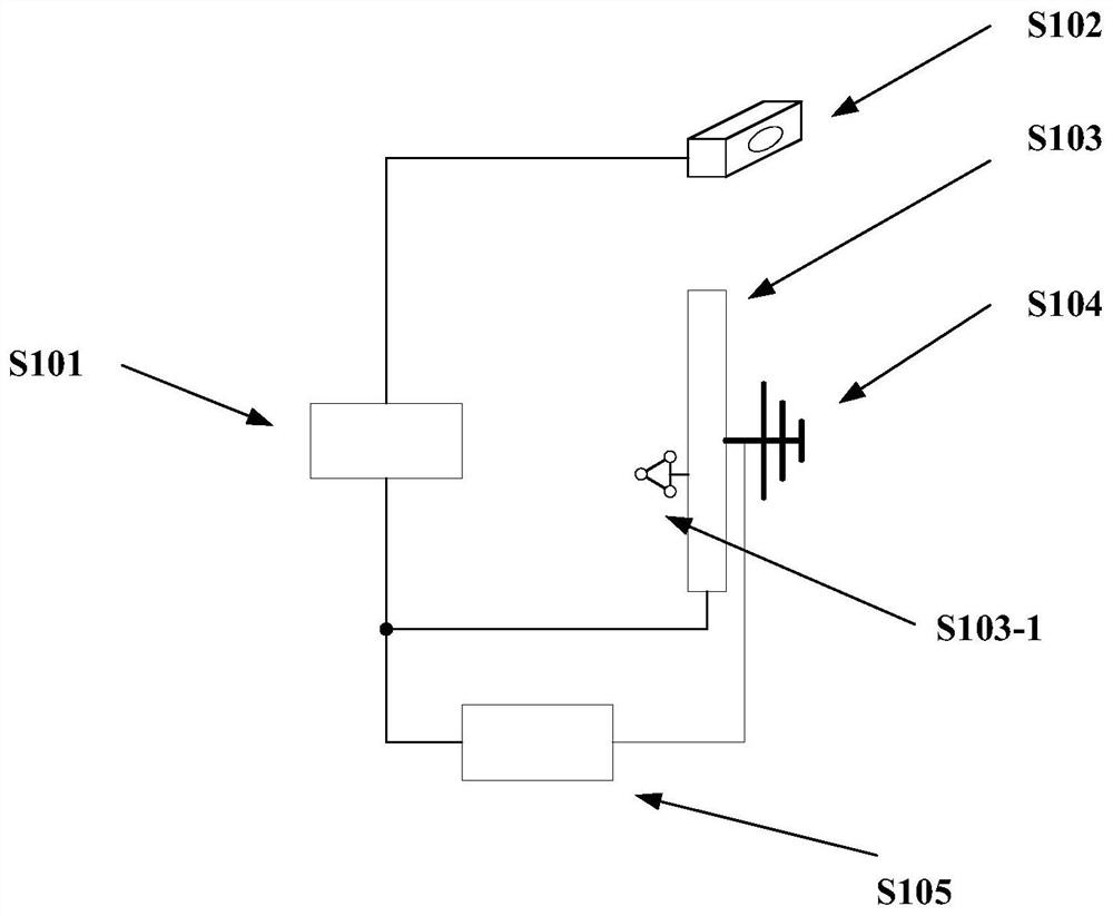
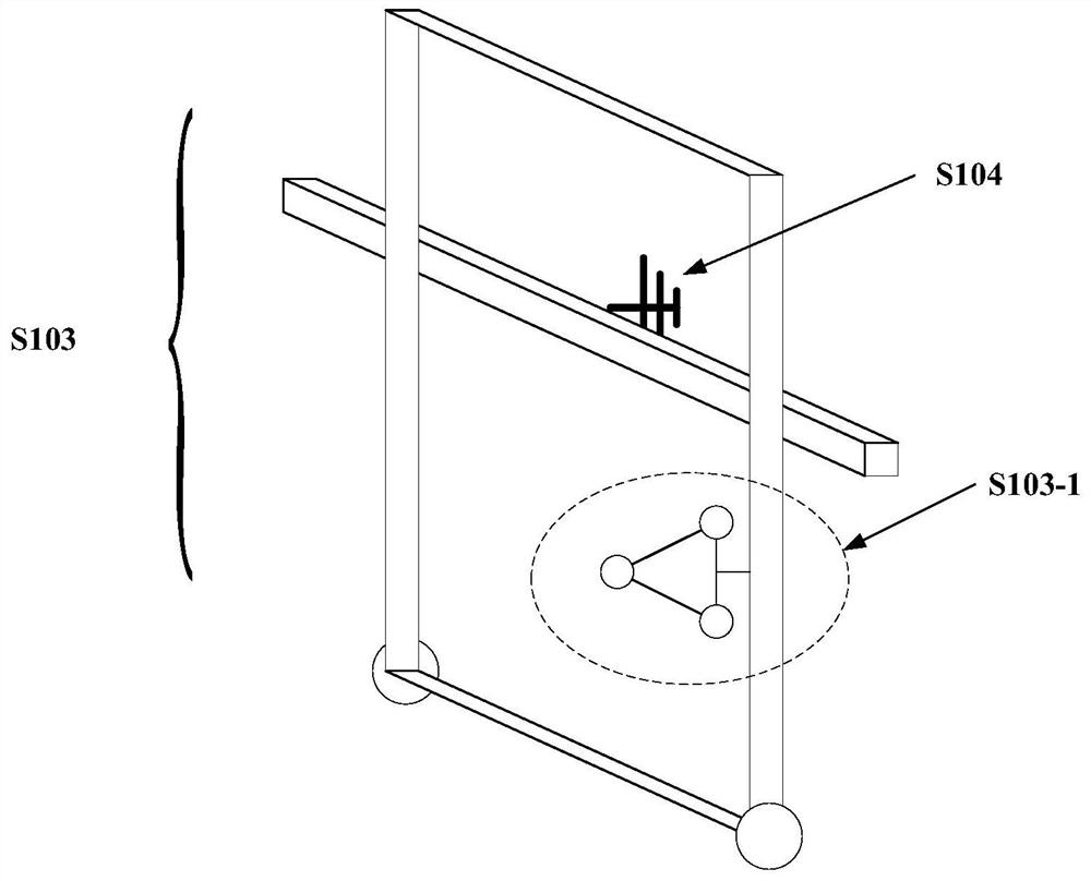
The invention discloses a 3D electromagnetic scanning system which can solve a problem of intuitive and visual representation of a three-dimensional spatial position relationship between a detection point and a measured object and spatial electromagnetic field distribution. The system comprises a control module, a 3D scanning module, a mobile scanning module, an electromagnetic probe and an electromagnetic signal receiving module. The control module acquires 3D contour information of a measured area and spatial position information of mark points from the 3D scanning module; the control moduleacquires position information of the electromagnetic probe on the mobile scanning module from the mobile scanning module; and the control module acquires scanning point electromagnetic signal frequency spectrum information received by the electromagnetic probe from an electromagnetic signal receiving module. And the control module converts the spatial position information of the mark points and the position information of the electromagnetic probe on the mobile scanning module to obtain a scanning point spatial position set of the electromagnetic probe, and finally fits the 3D contour information of the measured area, the scanning point spatial position set and the scanning point electromagnetic signal frequency spectrum information to output a 3D spatial electromagnetic distribution map.

Description

technical field [0001] The invention relates to the technical field of electromagnetic field intensity scanning, in particular to a 3D electromagnetic scanning system. Background technique [0002] The electromagnetic field intensity scan is used to obtain the electromagnetic field distribution in the space around the measured object, identify the strong electromagnetic field area, and then find the emission source that generates the strong electromagnetic field, so as to process the emission source, or take shielding measures to isolate the space radiation to reduce the space electromagnetic field intensity. [0003] The traditional electromagnetic field strength scanning is carried out by the tester holding the probe, and the automatic electromagnetic scanning system has emerged to solve the problems of poor accuracy and low test efficiency of traditional manual detection. There are two types of automated electromagnetic scanning systems: array scanning and mechanical scan...

Claims


Application Information

Patent Timeline
Patent Type & Authority Applications(China)
IPC IPC(8): G01R29/08
CPCG01R29/0871Y02A90/30
Inventor 徐军张华周怀安程丽丽董亚凯
Owner BEIJING INST OF SPACECRAFT SYST ENG
Learn More