Check patentability & draft patents in minutes with Patsnap Eureka AI!

Signal azimuth high-resolution estimation method based on sparse representation and reconstruction

A sparse representation, high-resolution technology, applied in positioning, design optimization/simulation, special data processing applications, etc., can solve problems such as insufficient processing ability of complex sound sources, loss of resolution ability, and inaccurate estimation of target parameters

Pending Publication Date: 2021-01-29
中国船舶重工集团公司七五0试验场
View PDF0 Cites 3 Cited by
  • Summary
  • Abstract
  • Description
  • Claims
  • Application Information

AI Technical Summary

Problems solved by technology

The disadvantage is that when the incident signals are close to each other, the signals may all appear in the main lobe of the beam, thus losing the ability to distinguish
In general, a large number of signal processing algorithms related to underwater acoustic signal azimuth estimation have been studied at home and abroad in recent years, but at present, most of the industry uses array signal processing related methods to obtain signal parameters, and the ability to distinguish adjacent incident signals is not strong enough. The processing power of the source is not high enough, and the estimation of the target parameters is not accurate enough

Method used


Image

  • Signal azimuth high-resolution estimation method based on sparse representation and reconstruction
  • Signal azimuth high-resolution estimation method based on sparse representation and reconstruction
  • Signal azimuth high-resolution estimation method based on sparse representation and reconstruction

Examples


Embodiment Construction

[0054] In order to enable those skilled in the art to better understand the technical solutions of the present invention, specific implementations thereof will be described in detail below in conjunction with the accompanying drawings.

[0055] Such as Figure 1 to Figure 7 A high-resolution estimation method for signal azimuth based on sparse representation and reconstruction is shown,

[0056] First, the sparse representation is performed based on the spatial sparsity of the signal azimuth, and the joint sparse vector is constructed using the norm;

[0057] Then, the dictionary matrix of sparse reconstruction is constructed, the sparse vector reconstruction is converted into a norm constraint problem, and the joint covariance matrix model is obtained;

[0058] Finally, the covariance matrix model is used to solve the norm minimization constrained problem to realize the signal orientation detection.

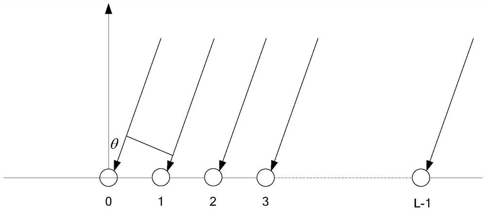
[0059] Further, the vector hydrophone uniform line array model is establi...


PUM


Abstract

The invention discloses a signal azimuth high-resolution estimation method based on sparse representation and reconstruction, and the method comprises the steps: firstly carrying out the sparse representation through the spatial sparsity based on a signal azimuth, and constructing a joint sparse vector through a norm; secondly, constructing a dictionary matrix of sparse reconstruction, convertingsparse vector reconstruction into a norm constraint problem, and obtaining a joint covariance matrix model; and finally, solving a norm minimization constraint problem by using a covariance matrix model to realize signal orientation detection. Expression redundancy does not exist, the characteristics of acoustic vector receiving signals are fully utilized, the number of signal sources does not need to be estimated, noise does not need to be suppressed, x-axis and y-axis information of the array receiving signals is jointly utilized, and the problems that when only acoustic pressure informationis utilized for azimuth estimation, precision is low, and signal resolution is difficult are solved; the signal azimuth estimation precision and the multi-signal resolution capability provided by theinvention are superior to those of a multi-signal classification method (MUSIC) and a traditional adaptive beamforming method (BARTLETT).

Description

technical field [0001] The invention relates to a high-resolution estimation method for signal azimuth, in particular to a high-resolution estimation method for signal azimuth based on sparse representation and reconstruction, which is mainly used for target detection and target positioning, and belongs to the technical field of array signal processing. Background technique [0002] Generally speaking, in the research of acoustic array signal processing, in order to calculate the orientation of the acoustic signal, most of the early researchers used the basic sound pressure hydrophone array, first through the signal for spatial sampling, and then for spatial spectrum estimation . With the rapid development of underwater acoustic technology, researchers have invented a new type of sound vector hydrophone, which is composed of a traditional sound pressure hydrophone and a particle velocity hydrophone, which can measure a point in the sound field space simultaneously and at the...

Claims


Application Information

Patent Timeline
IPC IPC(8): G01S5/20G06F17/15G06F17/16G06F17/18G06F30/20
CPCG01S5/20G06F17/15G06F17/16G06F17/18G06F30/20
Inventor 殷冰洁刘曲赵勰许霁
Owner 中国船舶重工集团公司七五0试验场
Features
  • R&D
  • Intellectual Property
  • Life Sciences
  • Materials
  • Tech Scout
  • Unparalleled Data Quality
  • Higher Quality Content
  • 60% Fewer Hallucinations
Learn More