Inspection robot laser navigation system and method

An inspection robot and laser navigation technology, applied in the field of inspection robots, can solve the problems of delay in operation information transmission, high deployment difficulty, affecting signal transmission, etc., and achieve the effects of fast adjustment speed, simple deployment, and simple calculation.

Pending Publication Date: 2021-01-29
上海许继电气有限公司 +2
View PDF3 Cites 0 Cited by
  • Summary
  • Abstract
  • Description
  • Claims
  • Application Information

AI Technical Summary

Problems solved by technology

[0007] 1. The magnetic track navigation system needs to be connected to the positioning system, and bad weather will affect the transmission of the signal, resulting in delay or loss of operation information transmission
[0008] 2. The magnetic track navigation system needs to lay magnetic strips under the inspection route, and excavation and installation of magnetic strips are required for the inspection section of the substation, which is difficult to deploy
In addition, it is necessary to regularly detect and maintain the magnetic stripe, otherwise the aging of the magnetic stripe will cause inaccurate positioning information and affect the automatic inspection.

Method used


Image

  • Inspection robot laser navigation system and method
  • Inspection robot laser navigation system and method
  • Inspection robot laser navigation system and method

Examples


Embodiment Construction

[0031] In order to make the object, technical solution and advantages of the present invention clearer, the present invention will be further described in detail below in combination with specific embodiments and with reference to the accompanying drawings. It should be understood that these descriptions are exemplary only, and are not intended to limit the scope of the present invention. Also, in the following description, descriptions of well-known structures and techniques are omitted to avoid unnecessarily obscuring the concept of the present invention.

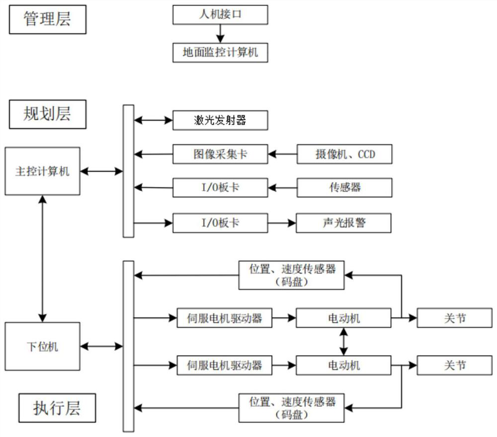
[0032] combine image 3 , the inspection robot laser navigation system of the present invention includes a management layer, a planning layer and an execution layer. The management set up the monitoring computer on the ground to receive the images sent by the main control computer, monitor the position of the inspection robot and whether the laser emitter is emitting laser normally. The planning layer includes the main ...


PUM


Abstract

The invention relates to an inspection robot laser navigation system and method. An inspection robot sets a laser to emit laser; a receiving plate is mounted on each straight road section after turning in a substation inspection route; the inspection robot sets a laser to emit laser; a receiving plate is mounted on each straight road section after turning in the substation inspection route; an image of the receiving plate is collected, and if the laser point position in the image is not located in the image center area, the visual angle of an image collection module is adjusted by a main control computer until the laser point position is located in the image center area; and if the laser point position deviates from the image center, the front wheel direction of the inspection robot is adjusted. A laser ranging technology is adopted to replace a magnetic guide rail navigation technology, so that the influence of severe weather on robot positioning is overcome; a magnetic guide rail does not need to be arranged in a transformer substation, and a laser receiver is relatively simple to arrange; the adjustment mode is simple in calculation, the adjustment speed is high, continuous adjustment is conducted after the vehicle passes through the curve, and the vehicle body is rapidly adjusted to move forwards along the straight line.

Description

technical field [0001] The invention relates to the technical field of inspection robots, in particular to a laser navigation system and method for an inspection robot. Background technique [0002] Substation inspection robot is the product of intelligent substation to replace manual inspection. Most of the substations are located in sparsely populated or even harsh environment areas. In addition to the development of unattended substations, only manual inspections are inefficient, poor in safety and reliability. Compared with the traditional manual inspection, the substation inspection robot mainly inspects the equipment under high voltage and unattended substations. [0003] At present, the inspection robot includes the following modules: walking module, image recognition module, and navigation module. Inspection robots can be divided into wheel-type inspection robots, crawler-type inspection robots and fixed-track inspection robots according to the walking mode. [00...

Claims


Application Information

Patent Timeline
Patent Type & Authority Applications(China)
IPC IPC(8): G05D1/02
CPCG05D1/0214G05D1/0219
Inventor 郑天齐赵德基王志轩王世奇尹海发周昊马梦冬黄保莉陈鹏高玉宝邬军军李建张漪沈永良杨明伟王嘉劼
Owner 上海许继电气有限公司
Why Eureka
Try Eureka