Energy collection device for ringing phenomenon of power device

A ringing phenomenon, power device technology, applied in the direction of output power conversion device, AC power input conversion to DC power output, irreversible AC power input conversion to DC power output, etc., can solve problems that do not consider the effective collection and utilization of energy , increase the power loss of the power loop, reduce the reliability of the converter, etc., to improve the electromagnetic interference problem, increase the impedance, and reduce the effect of the impact

Inactive Publication Date: 2021-01-29
HUNAN UNIV
View PDF2 Cites 2 Cited by
  • Summary
  • Abstract
  • Description
  • Claims
  • Application Information

AI Technical Summary

Problems solved by technology

However, most of the current EMI suppression technologies are only aimed at suppressing the voltage and current spikes and switching waveform ringing during the switching process of power devices to the greatest extent, and the energy generated by the ringing phenomenon is finally consumed on the resistance of the power loop, or in the form of The form of heat is consumed in the buffer bypass, without considering the effective collection and utilization of this part of energy, which increases the power loss of the power loop, reduces the reliability of the converter, and causes irreversible damage to the entire system

Method used


Image

  • Energy collection device for ringing phenomenon of power device
  • Energy collection device for ringing phenomenon of power device
  • Energy collection device for ringing phenomenon of power device

Examples


Embodiment Construction

[0026] In order to enable those skilled in the art to better understand the technical solution of the present invention, the present invention will be described in detail below in conjunction with the accompanying drawings. The description in this part is only exemplary and explanatory, and should not have any limiting effect on the protection scope of the present invention. .

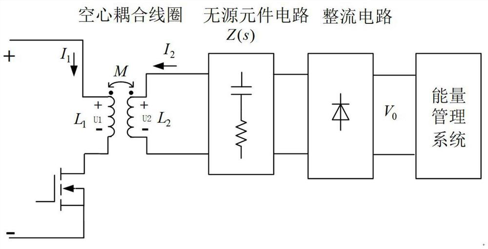
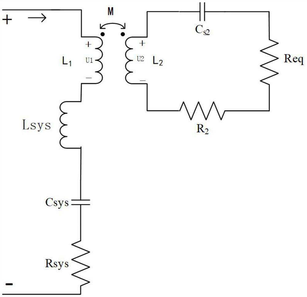
[0027] Such as Figure 1-Figure 5 As shown, the specific structure of the present invention is: an energy harvesting device aimed at the ringing phenomenon of power devices, the power device includes a converter, including an air-core coupling coil, a passive component circuit and a rectifier circuit;

[0028] The air-core coupling coil is connected to the power loop of the converter, and is used to generate an induced voltage when the current in the loop changes, and transfers the energy of the transient ringing phenomenon of the power loop switch to the secondary side for collection, and can Couplin...


PUM

PropertyMeasurementUnit
Thicknessaaaaaaaaaa
Thicknessaaaaaaaaaa

Abstract

The invention discloses an energy collection device for a ringing phenomenon of a power device, and the device achieves the energy collection of the ringing phenomenon of the power device through theconnection of a hollow coupling coil to a power loop of a converter on the premise that a system meets the electromagnetic compatibility. Electromagnetic interference energy generated by switching transient voltage and current waveform high-frequency ringing is sensed into a passive element on a secondary side, an alternating current signal is rectified into a direct current signal through a rectifying circuit, the direct current signal is stored and managed by a post-stage circuit, so that energy collection is achieved. And a PCB Rogowski coil is used as a hollow coupling coil, so that the influence of the coil on a power loop is reduced. Moreover, a passive element circuit is used for being coupled to a converter power loop to increase the impedance of the circuit, and suppression of converter switching waveform ringing can be realized by adjusting parameters of the passive element circuit. On the premise of not sacrificing the switching speed of the power device, the reliability problem and the electromagnetic interference problem caused by voltage and current spikes and ringing are solved.

Description

technical field [0001] The invention belongs to the technical field of electrical appliances, in particular to an energy collection device for the ringing phenomenon of power devices. Background technique [0002] As the core and foundation of power converter devices, power devices are widely used in new energy power generation, electric vehicles, smart grids, rail traction and other fields. However, due to the high voltage / current change rate generated during the fast switching process of power devices, the ringing phenomenon generated on the switching time domain waveform is the main cause of EMI noise, especially for SiC MOSFETs, SiC JFETs and GAN HEMTs. Representative wide bandgap semiconductor devices. Due to its higher switching frequency and faster switching speed, it is difficult to eliminate the ringing in the circuit for a long time, and the electromagnetic interference generated by it will affect the power device itself and other equipment in the circuit through ...

Claims


Application Information

Patent Timeline
IPC IPC(8): H02M1/44H02M7/06
CPCH02M1/44H02M7/066H02M1/0038
Inventor 杨鑫王紫茹李嘉文李桥
Owner HUNAN UNIV
Why Eureka
Try Eureka