Electricity zero-power-consumption protection circuit of dust collector and protection method thereof

A technology for protecting circuits and vacuum cleaners, applied in vacuum cleaners, battery circuit devices, circuit devices, etc., can solve the problems of consuming battery packs, wasting battery power, and unable to immediately realize zero power consumption of the circuit, and achieve the effect of saving electric energy

Pending Publication Date: 2021-02-02
SUZHOU CHUNJU ELECTRIC CO LTD
View PDF11 Cites 0 Cited by
  • Summary
  • Abstract
  • Description
  • Claims
  • Application Information

AI Technical Summary

Problems solved by technology

[0003] In some current rechargeable vacuum cleaners, after the shutdown and power failure, the circuit will continue to consume the power of the battery pack for a period of time, and the zero power consumption of the circuit cannot be realized immediately, thus wasting the power of the battery

Method used


Image

  • Electricity zero-power-consumption protection circuit of dust collector and protection method thereof

Examples


Embodiment 1

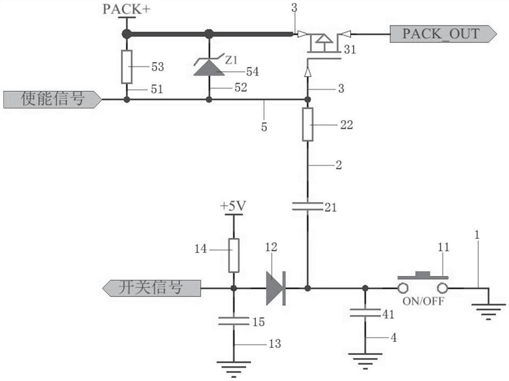
[0025] see figure 1 , the figure shows a zero power consumption protection circuit for a vacuum cleaner provided by Embodiment 1 of the present invention, which includes: a switch sub-circuit 1, on which a switch component 11 and a first diode 12 are arranged, and the first The diode 12 can specifically be a rectifier diode, one end of the switch sub-circuit 1 is grounded, the switch sub-circuit 1 is connected with a transmission circuit 13, the transmission circuit 13 is provided with a first resistor 14 and a first capacitor 15, and the transmission circuit 13 One end of 13 is connected to the power transmission unit, and the other end is grounded, wherein the power transmission unit can specifically be a battery pack outputting +5V current; the capacitor sub-circuit 2 is connected to the switch sub-circuit 1, and the capacitor sub-circuit 2 is provided with a second capacitor 21 and The second resistor 22 ; the MOS tube circuit 3 is provided with a MOS tube 31 , the MOS tub...

Embodiment 2

[0033] see figure 1 , the figure shows a zero power consumption protection circuit for a vacuum cleaner provided by Embodiment 2 of the present invention. On the basis of the above embodiments, this embodiment further makes the following technical solutions as improvements: the switch A grounding circuit 4 is also connected to the circuit 1, on which a third capacitor 41 is arranged. Through the setting of the above structure, a stable grounding effect of the switch sub-circuit can be realized.

Embodiment 3

[0035] see figure 1 , the figure shows a zero power consumption protection circuit for a vacuum cleaner provided by Embodiment 3 of the present invention. On the basis of the above embodiments, this embodiment further makes the following technical solutions as improvements: capacitor The enabling signal circuit 5 is also connected to the circuit 2, and the enabling signal circuit 5 is also connected to the single-chip microcomputer, and the enabling signal circuit 5 is also electrically connected to the MOS tube circuit 3 through the parallel first connecting circuit 51 and the second connecting circuit 52 respectively. A third resistor 53 is provided on the first connection circuit 51 , and a second diode 54 is provided on the second connection circuit 52 , and the second diode 54 may specifically be a Zener diode. Through the setting of the above structure, the effect of voltage stabilization can be realized, and the smoothness of the enable signal circuit can be ensured.


PUM


Abstract

The invention provides an electricity zero-power-consumption protection circuit of a dust collector. The circuit comprises a switch sub-circuit provided with a switch part and a first diode, wherein one end of the switch sub-circuit is grounded, the switch sub-circuit is connected with an electricity transmission sub-circuit, the electricity transmission sub-circuit is provided with a first resistor and a first capacitor, and one end of the electricity transmission sub-circuit is connected with a power transmission unit, and the other end is grounded; a capacitor sub-circuit which is connectedwith the switch sub-circuit, wherein a second capacitor and a second resistor are arranged on the capacitor sub-circuit; and a MOS transistor circuit which is provided with an MOS transistor, whereinthe MOS transistor circuit is connected with a positive electrode and a negative electrode of a battery pack, and the capacitor sub-circuit is connected with the MOS transistor. The invention furtherprovides a protection method. Compared with the prior art, the zero-power-consumption effect of the circuit can be achieved after the dust collector is shut down and powered off, and the electric energy of batteries is saved.

Description

technical field [0001] The invention relates to the field of vacuum cleaners, in particular to a zero-power consumption protection circuit for vacuum cleaners and a protection method thereof. Background technique [0002] Vacuum cleaners are cleaning equipment widely used in advanced human life and industrial production. It has been developed for more than 100 years since its birth. The working principle of the vacuum cleaner is to use the motor to drive the blades to rotate at high speed, generate air negative pressure in the sealed housing, and then suck the dust through the external suction pipe. [0003] In some current rechargeable vacuum cleaners, the circuit will continue to consume the power of the battery pack for a period of time after the power is turned off, and the zero power consumption of the circuit cannot be realized immediately, thus wasting the power of the battery. Contents of the invention [0004] In view of this, the present invention provides a zer...

Claims


Application Information

Patent Timeline
Patent Type & Authority Applications(China)
IPC IPC(8): A47L9/28H02J7/00
CPCA47L9/2805A47L9/2868A47L9/2889A47L9/28H02J7/0063
Inventor 韦启峰
Owner SUZHOU CHUNJU ELECTRIC CO LTD
Why Eureka
Try Eureka