
Plunger type valve

A plunger type and plunger technology, which is applied in the field of material conveying control valves, achieves the effects of convenient operation, improved wear resistance, and high material control efficiency

Pending Publication Date: 2021-02-02
BEIJING AEROSPACE PETROCHEM TECH & EQUIP ENG CORP LTD
View PDF11 Cites 0 Cited by
  • Summary
  • Abstract
  • Description
  • Claims
  • Application Information

AI Technical Summary

Problems solved by technology

[0003] However, for ordinary sampling and discharging valves, due to the limitation of use conditions, they are only suitable for sampling and discharging of fluid media under certain pressure differential conditions. Medium, under small pressure difference and harsh working conditions, it cannot play a good role in controlling the material flow direction

Method used


Image

  • Plunger type valve

Examples


Embodiment Construction

[0017] The present invention will be described in further detail below in conjunction with the accompanying drawings and specific embodiments. Note that the present invention is not limited to the embodiments to be described below.

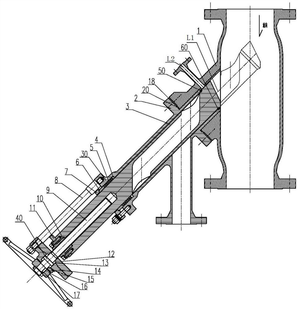
[0018] Such as figure 1 As shown, the plunger valve includes a main pipe platform 1, a valve body assembly 2, a plunger assembly, and a support assembly.

[0019] The main platform 1 is a pipeline with a special boss. A purge port and a purge device (not shown in the figure) are provided on the main pipe platform 1 . The purge flange of the plunger valve is located on the main pipe platform 1 and communicates with the main pipe platform 1 . In addition, the angle between the central axis L2 of the above-mentioned purge port and the central axis L1 of the valve body assembly 2 ranges from 45° to 135° near the sealing surface of the plunger, so that the seal can be effectively blown off when the valve is opened and closed. The medium at the surf...


PUM


Abstract

The invention discloses a plunger type valve. The plunger type valve is used for material conveying control and comprises a main pipe platform, a valve body assembly, a plunger assembly and a supporting assembly, the valve body assembly comprises a sealing face end inserted into the main pipe platform and sealed with the main pipe platform and a packing cavity end sealed with a plunger of the plunger assembly, the supporting assembly is connected with the packing cavity end, a Z-shaped cavity is formed in the plunger, when the plunger stretches into the main pipe platform from the valve body assembly, one end opening, close to the main pipe platform, of the Z-shaped cavity is connected with an internal flow channel of the main pipe platform, and the other end opening of the Z-shaped cavitycommunicates with a discharging opening of the valve body assembly, so that the opening position of the plunger type valve is guaranteed; when the plunger retracts into the valve body assembly, the conical sealing face, close to the main pipe platform, of the valve body assembly and the conical sealing face of the plunger form linear sealing, so that the closing position of the plunger type valveis guaranteed. According to the plunger type valve, high-performance material control can be achieved under the severe working conditions of high temperature, strong abrasion, particle flow and the like.

Description

technical field [0001] The invention relates to the field of material delivery control valves, in particular to a plunger valve. Background technique [0002] In the prior art, in terms of material conveying control, there are various valve bodies used, such as the slide valve disclosed in CN203699085, the specific ball valve disclosed in CN209977315, and the long barrel discharge valve disclosed in CN204328012. [0003] However, for ordinary sampling and discharging valves, due to the limitation of use conditions, they are only suitable for sampling and discharging of fluid media under certain pressure differential conditions. Medium, under small pressure difference and harsh working conditions, it cannot play a good role in controlling the material flow direction. Therefore, a valve with a special structure and a special material is required to cope with this special working condition. Contents of the invention [0004] The technical problem solved by the invention is:...

Claims


Application Information

Patent Timeline
Patent Type & Authority Applications(China)
IPC IPC(8): F16K5/04F16K5/08F16K5/22F16K31/60F16K25/00
CPCF16K5/04F16K5/0407F16K5/0435F16K5/0471F16K5/0492F16K5/08F16K5/225F16K31/60
Inventor 李强郭玉生杨欢赵宇琪冯建东张博文教忠翔
Owner BEIJING AEROSPACE PETROCHEM TECH & EQUIP ENG CORP LTD
Learn More