Thermal imaging body temperature intelligent monitoring system with built-in infrared calibrator
An intelligent monitoring and thermal imaging technology, applied in radiation pyrometry, instruments, sensors, etc., can solve the problems of reduced temperature measurement accuracy, low temperature measurement accuracy, poor flexibility, etc., to reduce false alarms and improve temperature measurement. Accurate, stable and accurate temperature measurement effect
- Summary
- Abstract
- Description
- Claims
- Application Information
AI Technical Summary
Problems solved by technology
Method used
Image
Examples
Embodiment 1
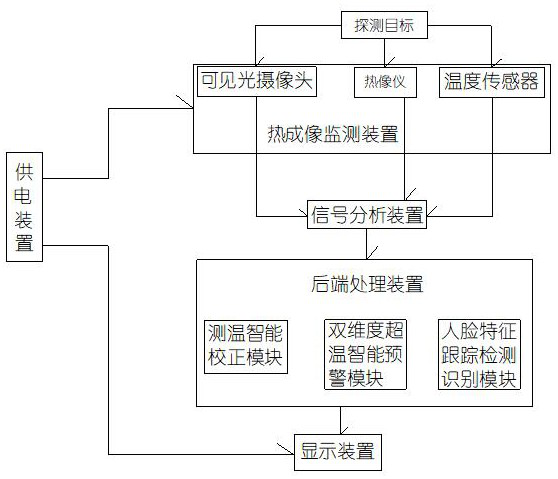
[0028] Embodiment 1, a thermal imaging body temperature intelligent monitoring system with a built-in infrared calibrator, including a deployment bracket, a thermal imaging monitoring device, a signal analysis device, a back-end processing device, a cloud platform, a display device and a power supply device, and the deployment bracket is detachable and installed In the monitoring place, the thermal imaging monitoring device is detachably installed on the upper part of the deployment bracket through the pan / tilt, and the output end of the thermal imaging monitoring device is electrically connected to the input end of the signal analysis device to transmit the collected monitoring signal to the signal analysis device for prediction. Processing, the output end of the signal analysis device is electrically connected to the input end of the back-end processing device, so as to transmit the pre-processed monitoring signal to the back-end processing device for subsequent operations, an...
Embodiment 2
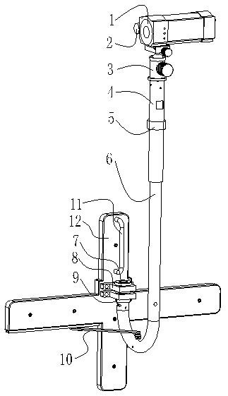
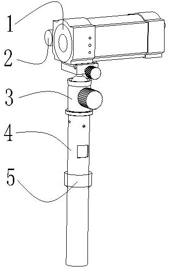
[0029] Embodiment 2, on the basis of Embodiment 1, the deployment bracket includes a bracket body 12, a support tube and an omnidirectional adjuster 3, the lower end of the support tube is connected to the front shaft of the bracket body 12, and the omnidirectional adjuster 3 rotates Sleeved on the top of the support tube, the pan / tilt is fixedly installed on the top of the omnidirectional adjuster 3 .
[0030] Further, the lower end of the support tube is connected to the front shaft of the support body 12 to realize 180-degree rotation at the front of the support body 12; The platform is installed on the upper part of the omni-directional adjuster, and the omni-directional adjuster is manually operated to realize the 360-degree omni-directional rotation of the thermal imaging monitoring device on the Z axis; the omni-directional adjuster includes a rotating sleeve, a locking bolt, and a support tube There is a ring-shaped rib on the upper part of the shaft, the rotating slee...
Embodiment 3
[0032] Embodiment 3, on the basis of Embodiment 2, the support pipe includes a U-shaped pipe 6 and a straight pipe 4, one end of the U-shaped pipe 6 is connected to the front shaft of the bracket body 12, and the other end of the U-shaped pipe 6 passes through The hand screw nut 5 is slidingly socketed with the lower end of the straight pipe 4 to realize telescopic adjustment; the upper end of the straight pipe 4 is movably socketed with the lower end of the omnidirectional adjuster 3 to realize omnidirectional rotation.
[0033] Further, the support tube is made of aluminum tube, copper tube, stainless steel tube, etc. Any material can be used. Preferably, the support tube is made of aluminum material, which is low in cost and light in weight.
[0034] Further, at least one bearing support 8 is fixedly installed on the front part of the bracket body 12, and the rotating shaft 7 is vertically embedded in the bearing support 8, and the upper end of the rotating shaft 7 is provid...
PUM
 Abstract
Description
Claims
Application Information
 - R&D
- Intellectual Property
- Life Sciences
- Materials
- Tech Scout
- Unparalleled Data Quality
- Higher Quality Content
- 60% Fewer Hallucinations
Browse by: Latest US Patents, China's latest patents, Technical Efficacy Thesaurus, Application Domain, Technology Topic, Popular Technical Reports.
© 2025 PatSnap. All rights reserved.Legal|Privacy policy|Modern Slavery Act Transparency Statement|Sitemap|About US| Contact US: help@patsnap.com


